Stranger Things install
Time to install: 10–15 minutes.

⚠ Three things you MUST know before starting
- Never connect the Red/Green flasher cable to a GI bulb. The light bars will overheat and warp.
- Some “flashers” don’t actually flash — they’re on more than they’re off. Don’t trigger from those either.
- Install at your own risk. If you’re not comfortable working inside your pinball machine, ask a knowledgeable friend or technician.
If you’re unsure about anything, email us before connecting. We’d rather help you up front than have a damaged module to deal with.
Watch the video above, then proceed to Step 1.
Step 1
Remove the playfield glass and balls from the machine, then raise the playfield vertical.
Standard
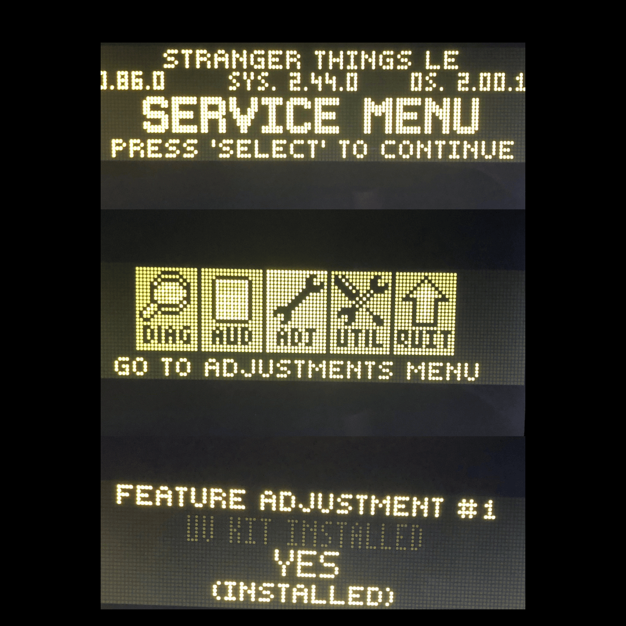
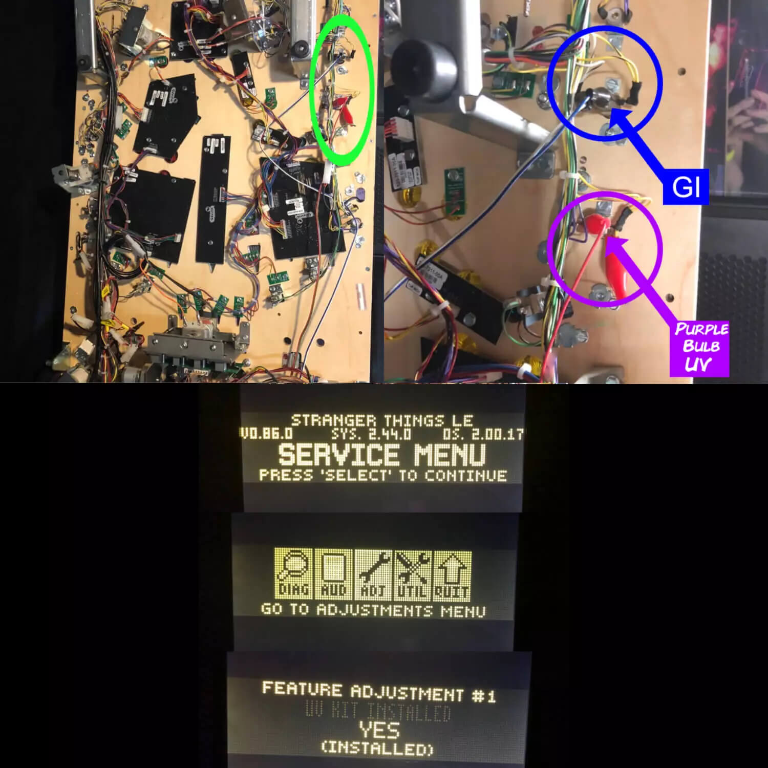
First going into Settings/ADJ/Feature Adjustments(ST) by opening the coin door and use the buttons to navigate to that menu. Turn on the “UV Kit Installed” change it to “YES” or this kit WILL NOT work. Then you will locate your GI and Flasher cables:

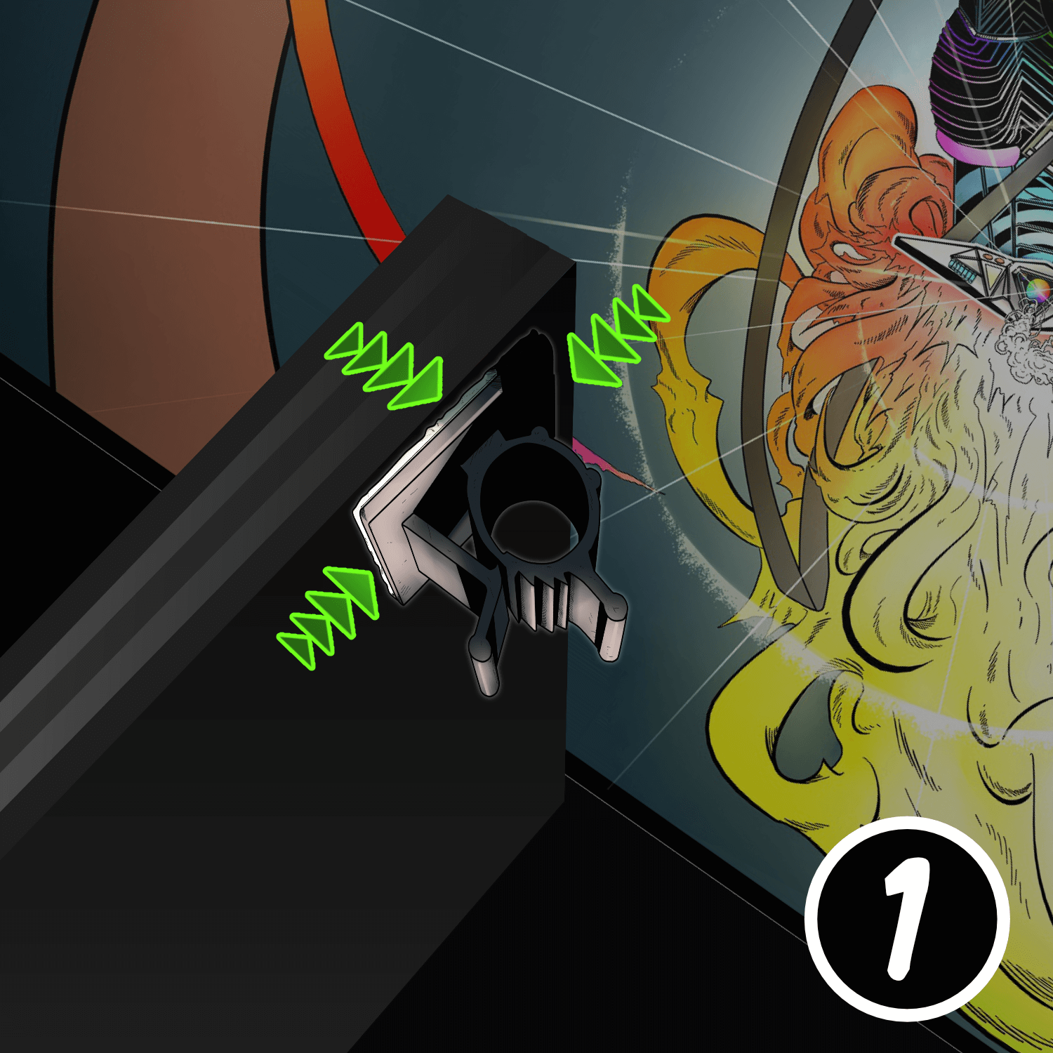
GI: Connect the BLUE/WHITE cable’s alligator clips to a White GI Bulb (polarity is not important so it doesn’t matter which side you connect them to) and plug the other end of this cable into the USB connection on the GI Module(black heat shrink with USB connection). UV+Glow: This is the RED/GREEN cable coming from the same USB GI module mentioned above and this will go to the #172 Lower Right Ramp trigger which is the flasher on the right side near the ramp. You can visually locate this flasher by opening the coin door and going into Settings/Diag/Lamps and cycle to #172 using the volume buttons. Be sure to pull out white the high voltage switch buttons located near the hinge of the coin door or the flashers will not work during this Settings mode. Even easier, you can see the #172 flasher location indicated by the pic below. Once you find it then use the “Y” Konekt adapter(attached to the Red/Green cable) supplied with the kit which will allow you to simply unplug the factory flasher and plug it inline with this flasher.
Fusion Connections will be like this:
164 Eject (Blue/Black cable)
165 Left Orbit (Red/Black cable)
172 Lower Right Ramp (Green/Black cable)
(White/Black cable not used)
(UV+Glow the Red/Green cable not used)
True UV Reveal Flasher: Connect the other cable to a Purple GI Bulb with the alligator clips and polarity does not matter as always with any connections you make.
Note: In some cases the alligator clips may not be able to reach clip cleanly onto the terminals due to the black heat shrink that is on them from the factory. If this is the case, simply get a small flathead screwdriver and back off the factory heat shrink to make room for the clips to grab onto the terminal. Be sure to do this with the game “Off” of course. Make sure this connection is solid and firm due to the fact that if these become detached, the UV will stay on and get warm. This will make the light bar to get warm and lose bond with the cabinet wall along with causing damage due to the heat. You will see it starting to get very warm starting at the rear of the light bars where the ribbon cable meets the light bars. This means that you either don’t have the Red/Green cable for the IV flasher or the UV Reveal lights hooked up properly. If you see this occur, unplug the lights until you recheck all of your steps so that you can at least keep the lights working as opposed to unrepairable cosmetic damage, which is the first first stage of having these not installed properly. This kit is real UV so it’s Very important!! You must have your machine powered on and off by a wall switch or a power strip otherwise the UV will stay on all the time and caused this type of damage. Please DO NOT skip or overlook this step. It’s very important Otherwise, you will be needing to buy another one of these kits to replace this one. Keep in mind that power should be off completely(this applies to all installs as usual) to the machine while you’re doing this install because the UV lights will be triggered during the install which can cause that damage also
Step 2
Plug in power
Connect the power supply cable into the service port, located behind the right speaker in the backbox.
Step 3
Connect the cables to the Pin Stadium GI module
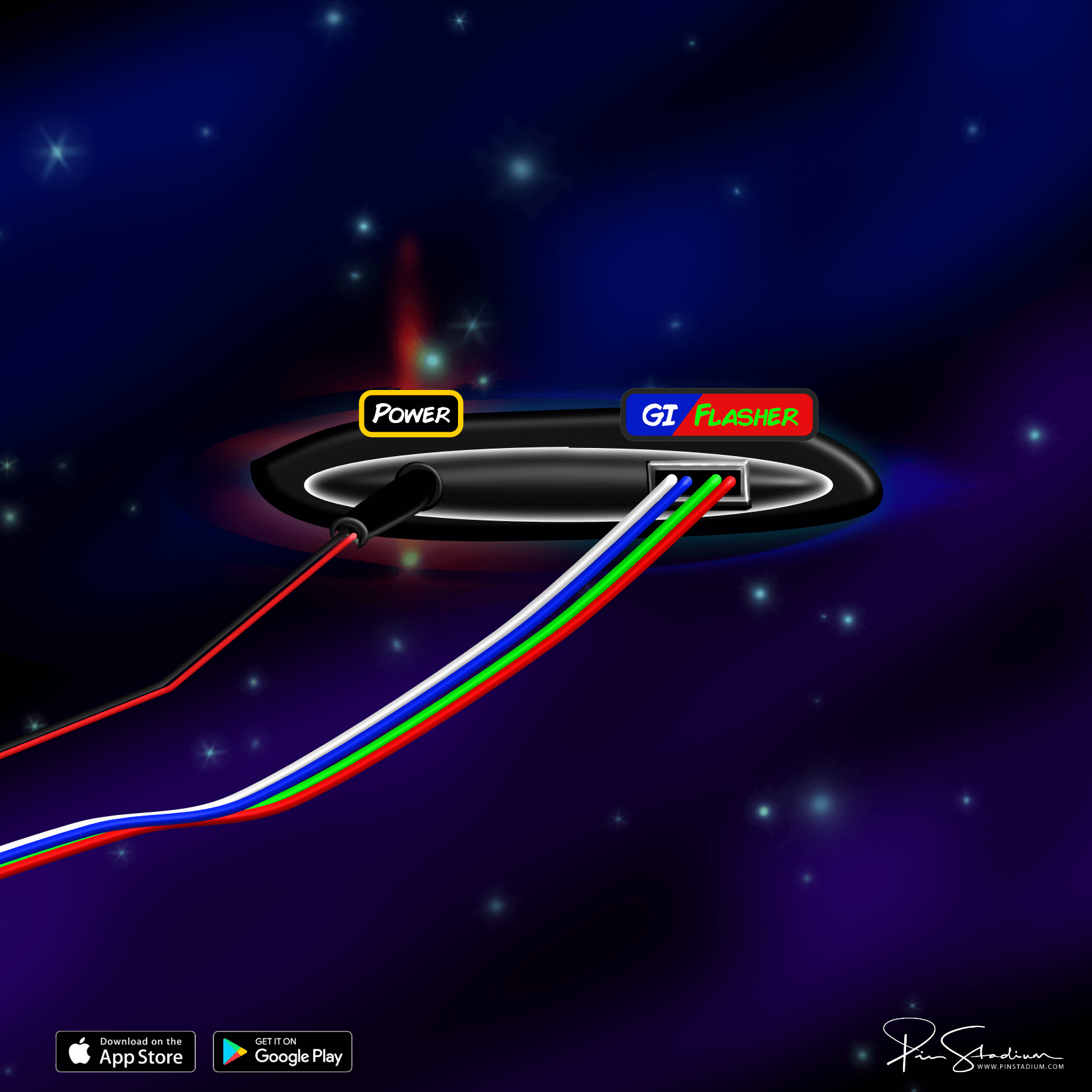
Lower the playfield to its resting angle and rest the light bars on top. Plug the power, GI cable, and Flasher cable into the Pin Stadium GI module as shown:
If your module uses a non-USB plug, use this diagram instead.
Step 4
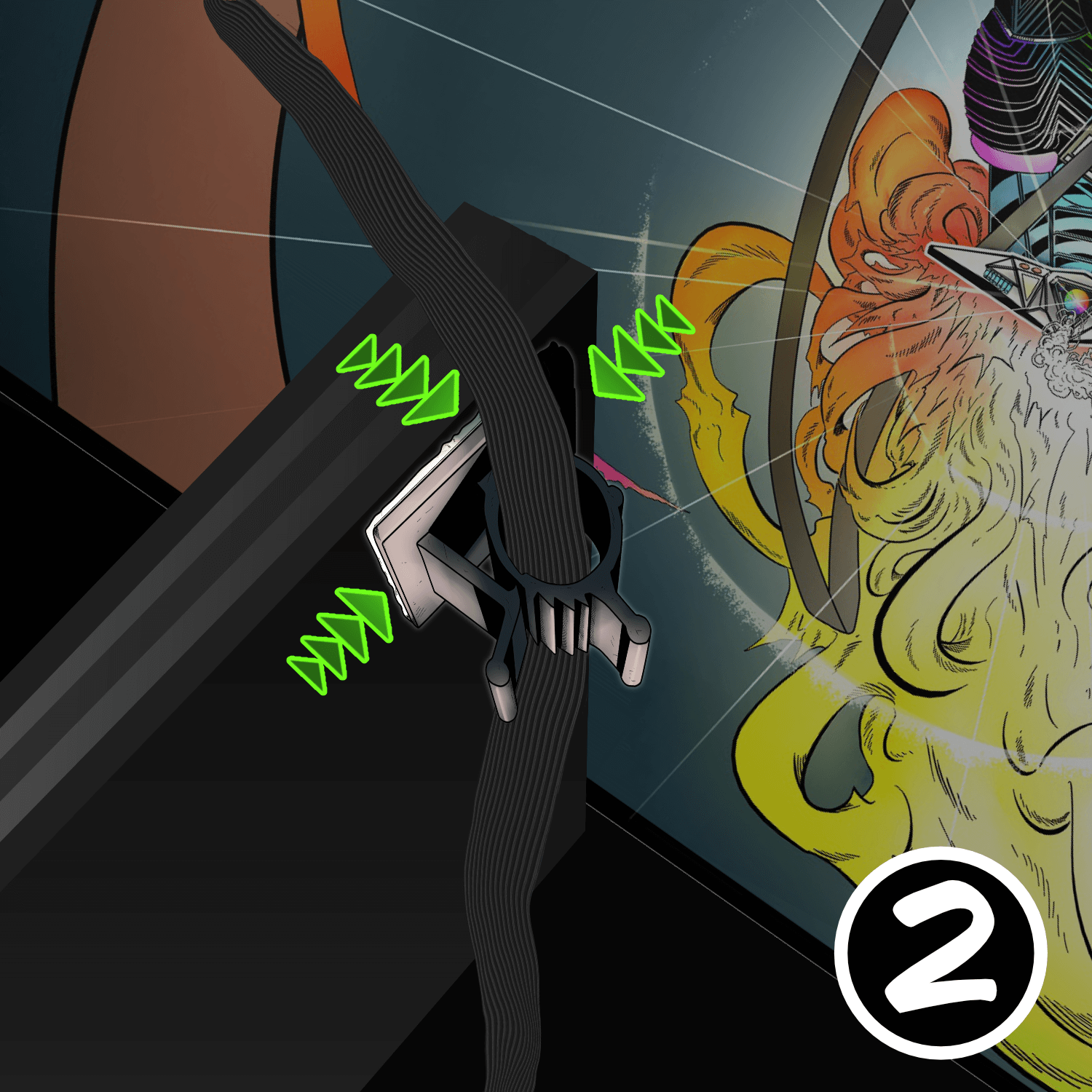
Mount the ribbon-cable clamps
Place the GI module over the backboard, into the bottom of the cabinet, out of the way of any moving parts.
From the accessory packet, stick the small adhesive ribbon-cable clamps to the upper-left and upper-right corners on the back of the playfield. These guide the ribbon cables and prevent pinching.
Pro tip: fold the ribbon cable in half lengthwise — it slides into the clamp easier. Leave about 6–8 inches between the clamp and the back of the light bar (with about 1 inch of slack).
Step 5
Prep the cabinet walls
Lower the playfield to its level resting position. Use the included alcohol wipe to clean the cabinet wall just below the playfield-glass track — about 2 inches down. It must be completely dry and dust-free for the Magna-Mounts to bond.
Position the lights 1/16″ below the glass channel, far enough back to hide the ribbon cable and clear the backbox hinge. Tuck the ribbon cable behind the back playfield-glass receiver channel.

Step 6
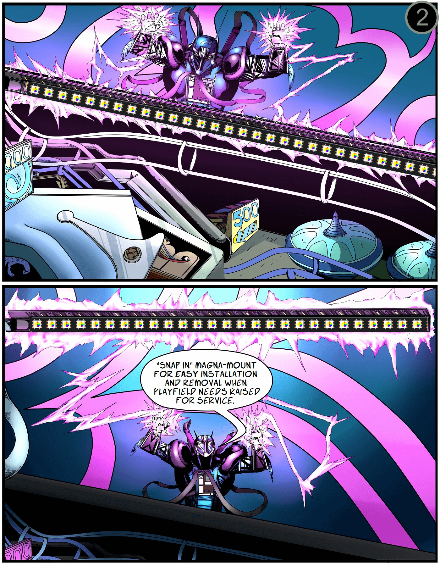
Peel, press, repeat
Carefully peel off the white protective backing on the Magna-Mount. Align the lights 1/16″ below the channel, far enough back to hide the ribbon cable and clear the backbox hinge.
Press firmly along the entire length of the light channel for maximum adhesion. Repeat for the opposite side.
Take your time — a sloppy bond means the lights will sag or fall.
Step 7 (Finished)
You’re done — light it up
Raise the playfield back to play position and replace the balls. Attach the light bars to their Magna-Mount backs on the cabinet sides, then replace the glass and lockbar.
Next: download the app and customize your lights
Enjoy the Stranger Things vibes. Post a “before / after” on the Pin Stadium Pinside thread — we love seeing them.
Questions? Email me directly.