Neo “X” Panels install
Time to install: 10–15 minutes.

What’s different about this install: Neo “X” Panels mount into a factory recessed slot on the side of the cabinet — no Magna-Mounts needed. You’ll also be running a second module (Lumi-Motion) for motion-reactive lighting.
⚠ Read this before starting
- USE THE NEW DECORATIVE PANELS — not the original “L-shaped” ones that shipped first. The new style with screw holes and holographic finish was mailed to everyone — wait for it. Don’t try to install with the old panels.
- This is a different install from the Neo Atom / Fusion. Don’t try to figure it out from memory — follow these steps or you’ll damage the panels.
- Never connect the Red/Green flasher cable to a GI bulb. The light bars will overheat and warp.
- Orion’s Belt flasher lights (Concert Edition only): these come pre-programmed. Don’t try to reprogram colors — you’ll damage the module.
Installing the standard Neo Atom? Use the Neo Atom install guide.
For per-machine flasher recommendations: Specific Flasher Connections by Machine.
If you’re unsure about anything, email us before connecting.
The video above is a general reference — the Neo “X” Panel install is similar to Neo Atom but with two key differences: (1) no Magna-Mounts (the panels sit in a factory recess), and (2) there’s a second Lumi-Motion module to mount and configure. Use the video for the GI/Flasher and app-setup parts, but follow the written steps below for the panel-specific work.
Light bars MUST be installed with the playfield raised. Do not try to install them with the playfield down or you’ll damage the LEDs and cables. Follow the steps in order.
Step 1
Set up the panels and connect to your machine
If your machine has factory side-wall lights, remove them first (unscrew the panels, pull the metal LED holder, disconnect the cables). You can sell them on a pinball marketplace — you won’t need them anymore.
Open the machine: release the lockdown bar latches, remove the glass to a soft surface, remove the balls (or tuck a rag in the trough), and raise the playfield to its full upright position.
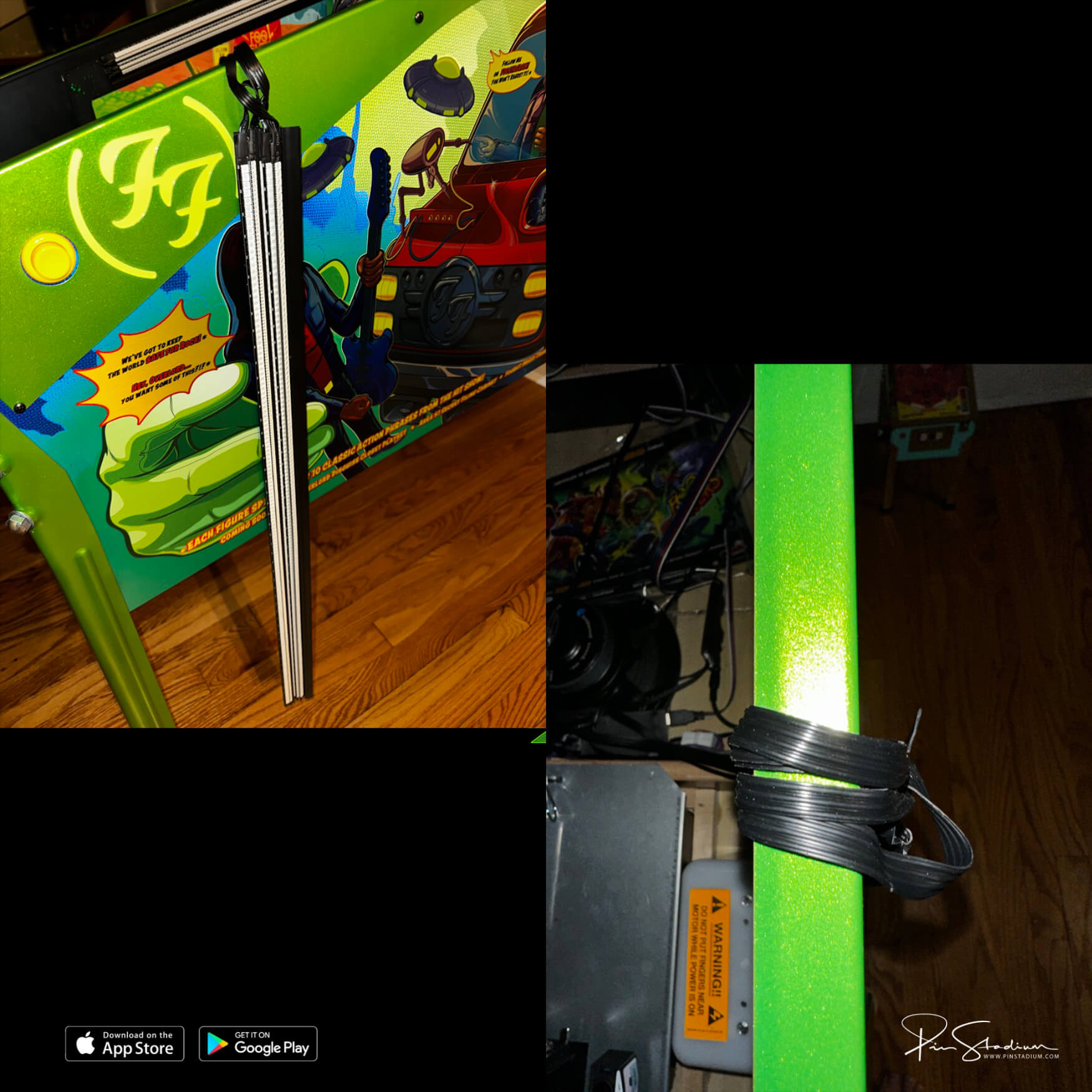
Rest the light bars in the bottom of the cabinet so they hang over the sides:
Connect the GI cable (Blue/White)
Find the black heat-shrunk GI module with the USB input. Connect the Blue/White cable’s alligator clips to a white GI bulb. On Sterns this bulb usually has a yellow wire with a black stripe. You may need to push or peel back the heat shrink to get clean access to the metal terminals.
Connect the Flasher cable(s) — pick your game
The Red/Green UV+Glow cable from the GI module goes to a flasher on your machine. The additional flasher module has its own per-game connections. Pick your game below:
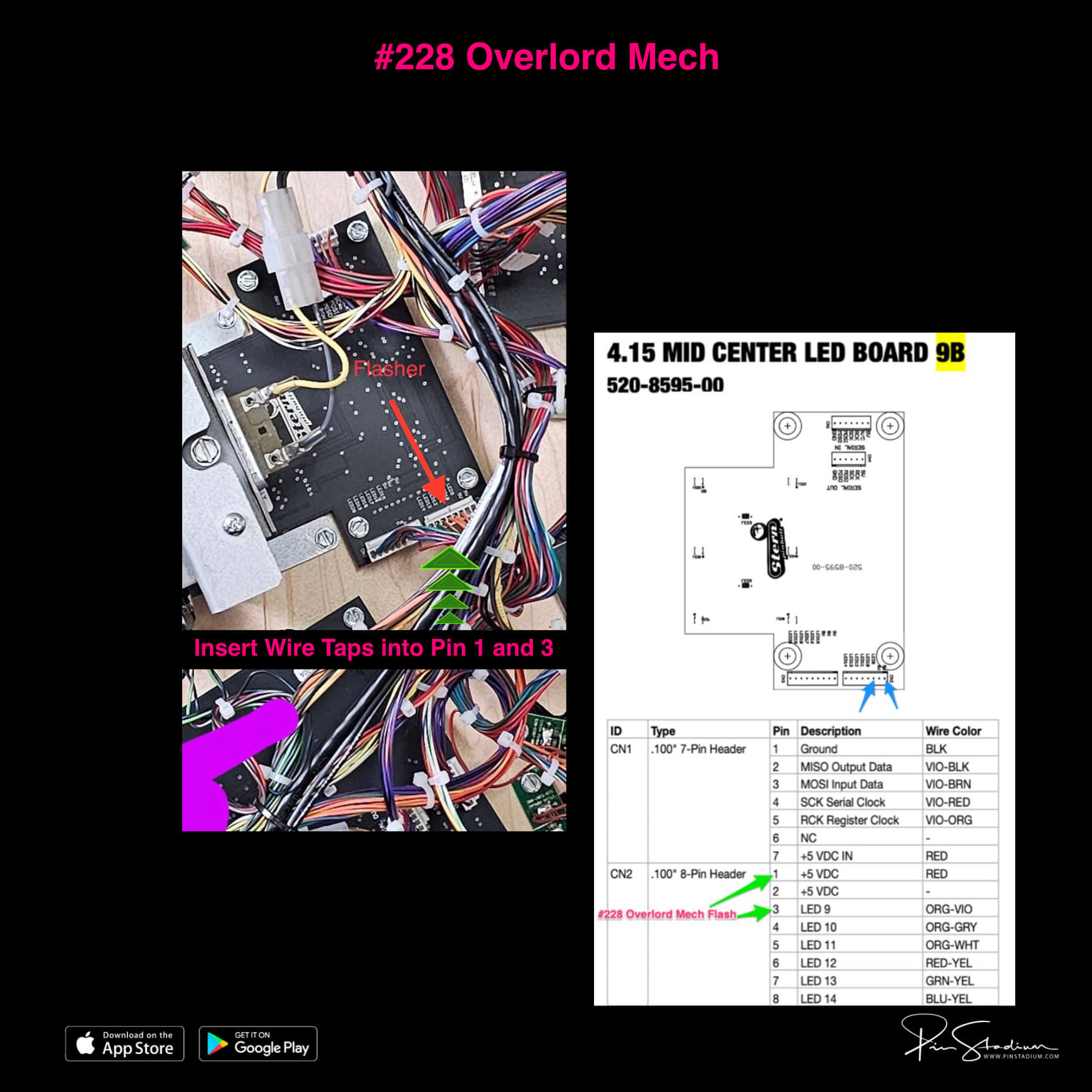
UV+Glow (Red/Green) from GI module: #228 Overlord Mech
From the second flasher module:
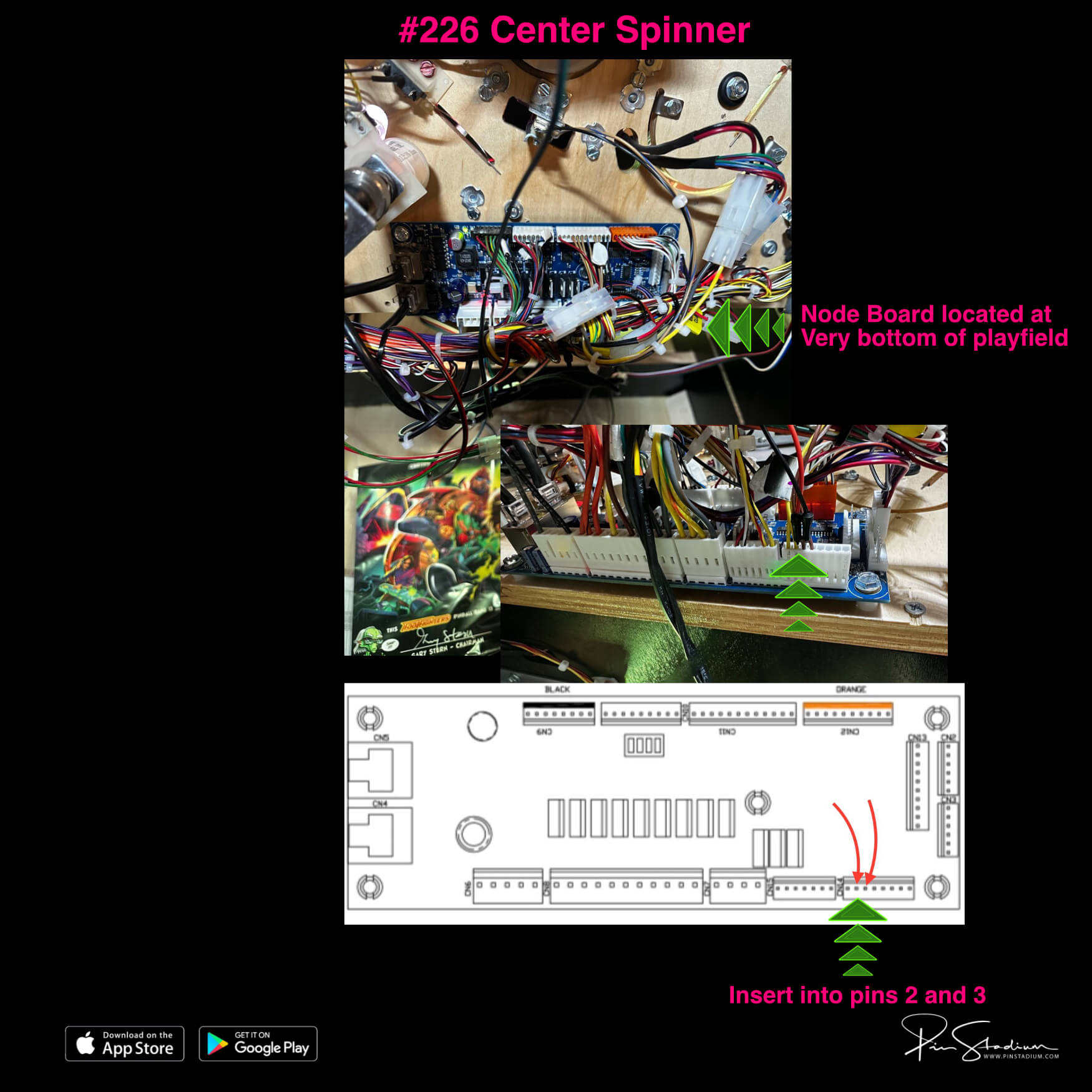
- #226 Center Spinner → Green/Black cable
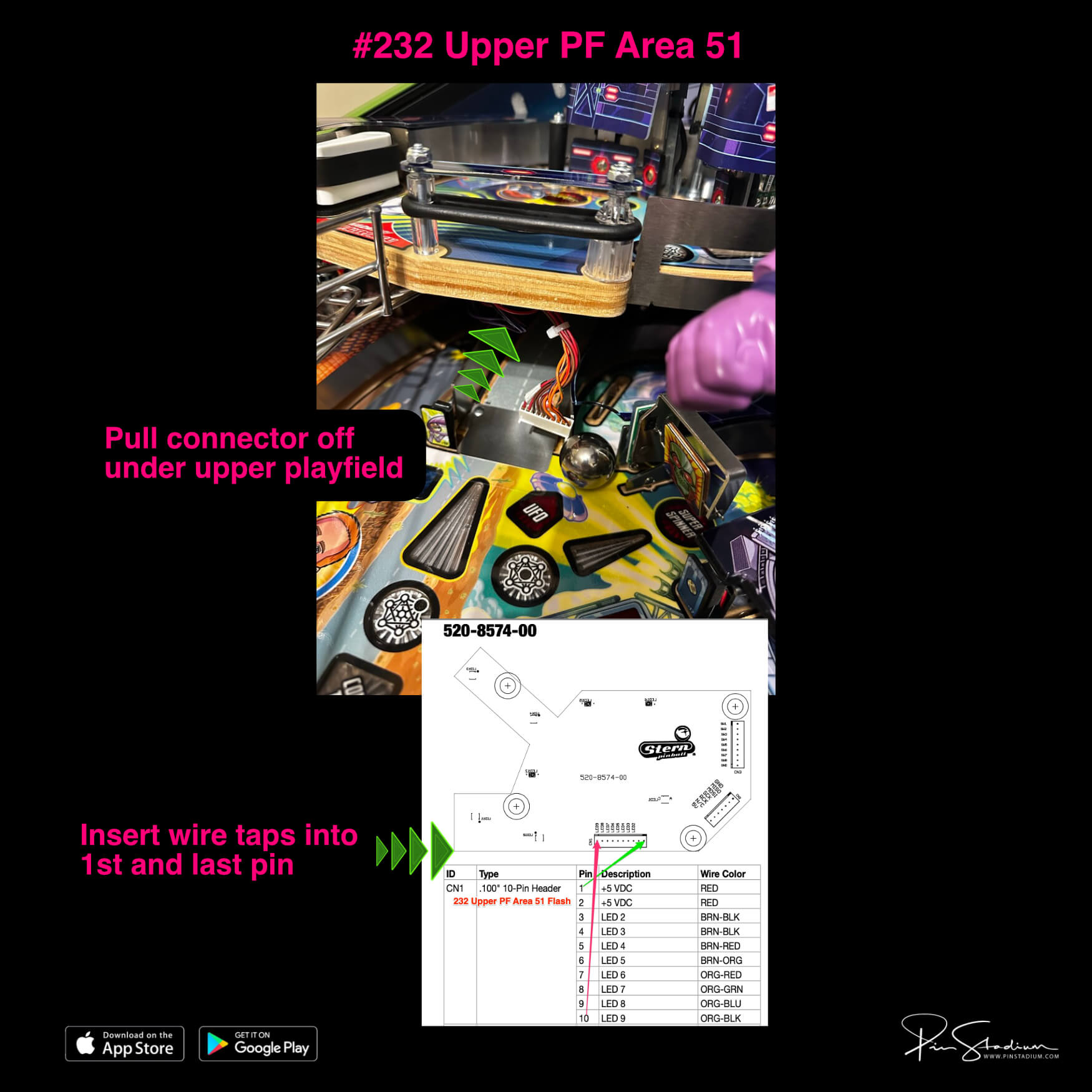
- #232 Upper PF Area 51 → Blue/Black cable (route through the backboard opening; tape down to keep clear of the ball during play). Pro version: use the supplied 2-pin “Y” adapter instead.
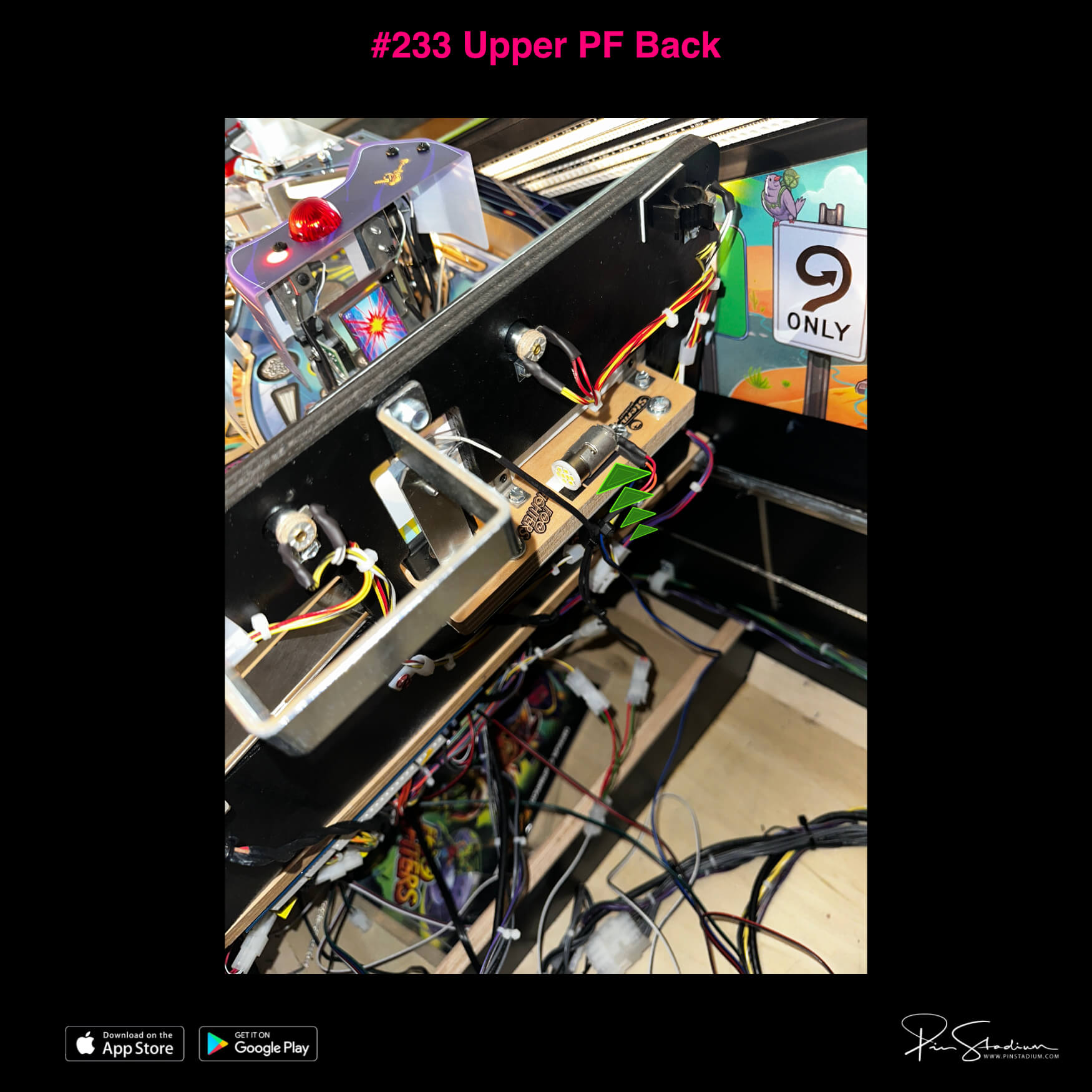
- #233 Upper PF Back → Red/Black cable (Premium/LE only — Pro doesn’t use this)
- #167 Upper Right → UV+Glow Red/Green cable
- #168 Lower Right → Green/Black cable
- #160 Left Sling → Red/Black cable
- #161 Right Sling → White/Black cable
- #165 Upper Left → Blue/Black cable
- #167 Backpanel → Red/Green UV+Glow cable
- Electric Magic RGB → remaining cables
- White/Black cable → not used
- #167 Backpanel → Green/Black cable (2-pin Molex)
- #168 Left Eject flasher → Red/Black cable (wire-tap Brown/Red and Yellow wire)
- #169 Left Spinner → Blue/Black cable (optional; requires soldering — email for details)
- White/Black cable → not used
- Red/Green cable → not used
- Open the coin door and pull out the white interlock switch (enables flashers in service mode).
- Go to Settings → Diag → Lamps → Flash.
- Cycle through flashers with the volume or flipper buttons — the screen shows the flasher number and the factory wire colors.
- Confirm by unplugging the flasher’s connector at the bulb. The bulb stops flashing — that’s your flasher.
Never trigger from a shaker motor on a Stern machine.
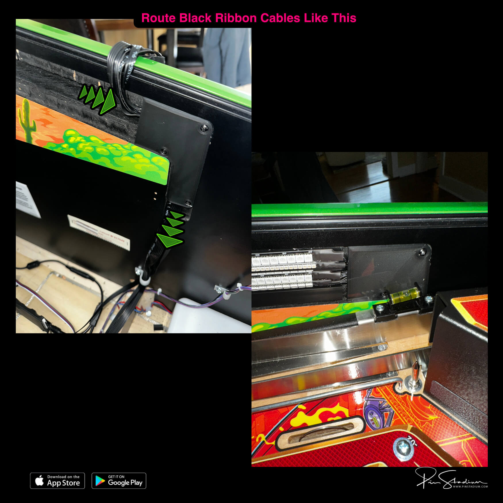
Route cables and mount the decorative panels
Line up the black ribbon cables with the recessed channel where the factory side lights went. Press them all the way in — you must not have cables sticking out for the next step.
Place the decorative panel over the channel (cables underneath). Hold firm pressure on the panel so cables don’t pop out. Drive in the 3 small black screws with a small Phillips. If you suspect any cable has snuck out from under the panel, redo it — otherwise you’ll screw into the cable.
Do this for both sides.
Lower the playfield (slowly!) and snap in the light bars
Once the playfield is down, snap the light bars into their recesses. Start from the rear and work toward the flippers. Reach through the coin door and gently pull each grouping of ribbon cables down behind the decorative panel as you go — you want just the right slack so the bars seat cleanly. Too much slack and the bars won’t snap in; too little and the cables will pull.
Repeat on the opposite side.
Step 2
Mount the Lumi-Motion module
Plug the supplied power splitter into the service port behind the right speaker on the backbox. Plug both power supplies into the splitter, running the cables down into the bottom of the cabinet so you can access them later.
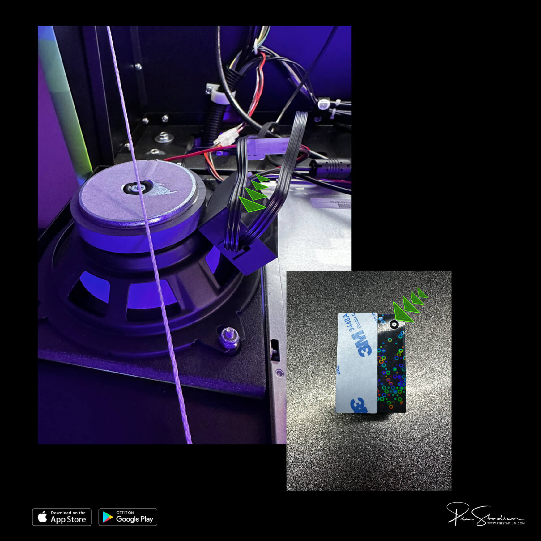
Peel the 3M backing off the Lumi-Motion wireless sensor box and mount it on the back of the speaker:
- The small port faces down, into the speaker opening.
- The 3M adhesive sits on the outside radius of the speaker.
Step 3
Set up the Lumi-Motion in the app
Plug power into only the Lumi-Motion module (the black holographic-pattern box). Unplug your other Pin Stadium modules temporarily so you don’t see multiple “LEDNet***” networks at once — it’ll save you confusion. (Always set up one module at a time.)
Open the Pin Stadium app and add the Lumi-Motion as a new device:
- Connect to the “LEDNet******” Wi-Fi for this device.
- Add it in the app and name it something obvious like “game name Lumi”.
- Go to the Music tab at the bottom → select Device Microphone → hit Play.
- Tap Light Screen Mode and select the first colorful spectrum setting (see screenshot).
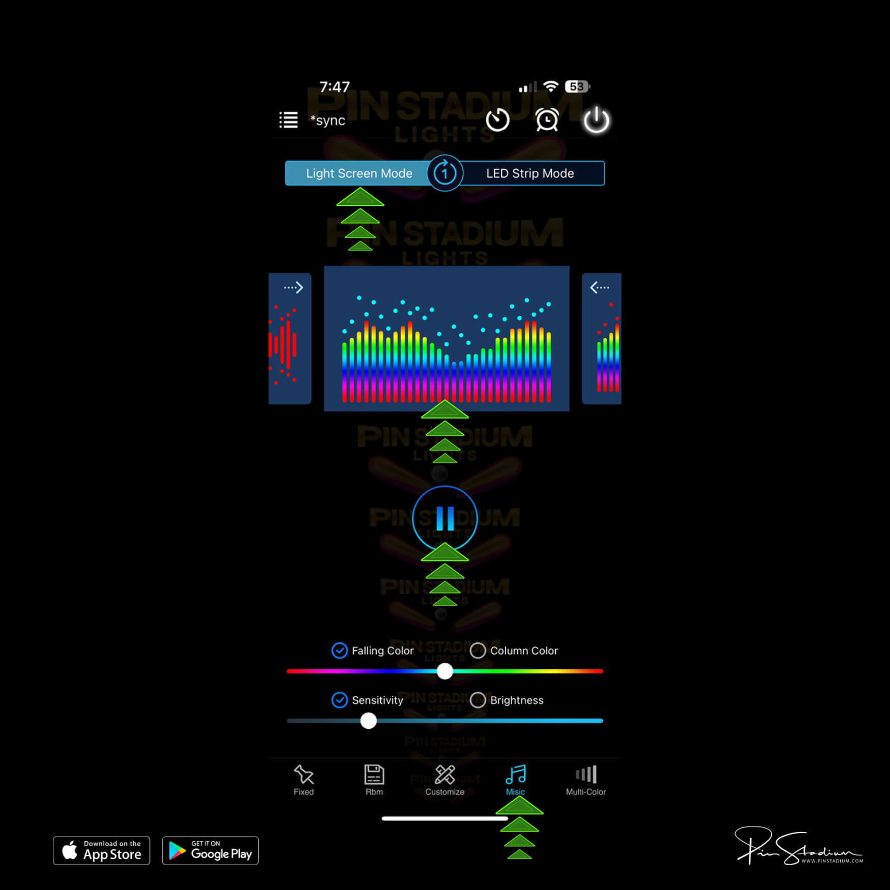
Customization: feel free to try other effects and patterns. There’s no documentation — just change settings and see the effects. The spectrum setting above gives the best overall results in our experience, but explore.
You’re done! Close the machine up, reinstall the lockdown bar, put the balls and glass back in, and play.
Questions? Email us for an instant response.
Step 4
EMAIL US for help please and you will get an instant response. Always happy to help!!