Quick start — Neo “X” Atom / Neo Atom install
Time to install: 10–15 minutes.

What you’re doing in 30 seconds: the Pin Stadium harness has two trigger cables (GI = Blue/White, Flasher = Red/Green) that clip onto two existing wires in your machine. Plug power into the service port, mount the light bars, and you’re done.
⚠ Three things you MUST know before starting
- Never connect the Red/Green flasher cable to a GI bulb. The light bars will overheat and warp.
- Some “flashers” don’t actually flash — they’re on more than they’re off. Don’t trigger from those either.
- Install at your own risk. If you’re not comfortable working inside your pinball machine, ask a knowledgeable friend or technician.
Installing the Fusion version? Use the Neo Fusion Atom install guide instead.
Already know the basics? Skip to Specific Flasher Connections by Machine.
If you’re unsure about anything, email us before connecting. We’d rather help you up front than have a damaged module to deal with.
Step 1
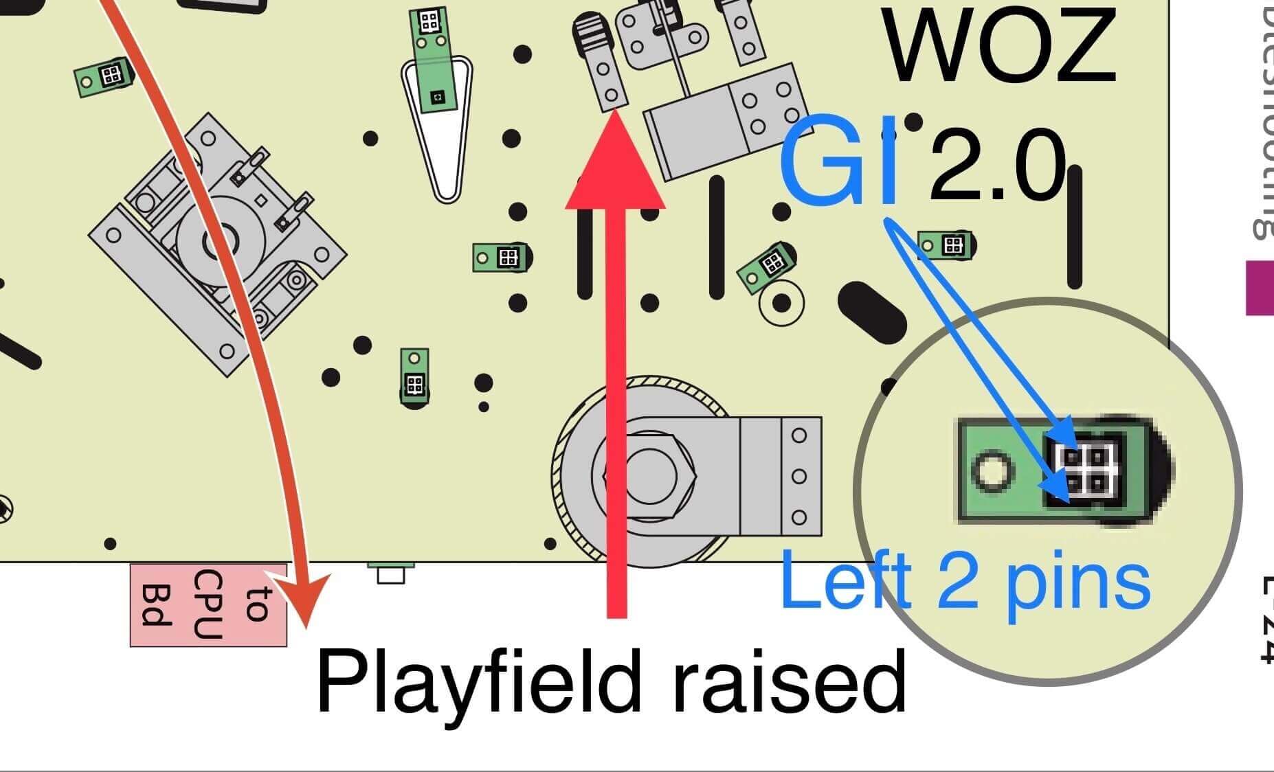
Raise the playfield and identify your two connection points
Remove the playfield glass and balls, then raise the playfield to its vertical service position.
You’ll connect two cables from the Pin Stadium harness:
- GI cable — Blue/White → any white GI bulb (always on during play). Polarity doesn’t matter.
- Flasher cable — Red/Green (UV+Glow) → a real flasher (briefly on during gameplay events). Polarity doesn’t matter.

Find your machine in the tabs below. Use the Standard tab for most pinballs (Stern, Williams, Bally). If your manufacturer is listed in another tab, use that instead.
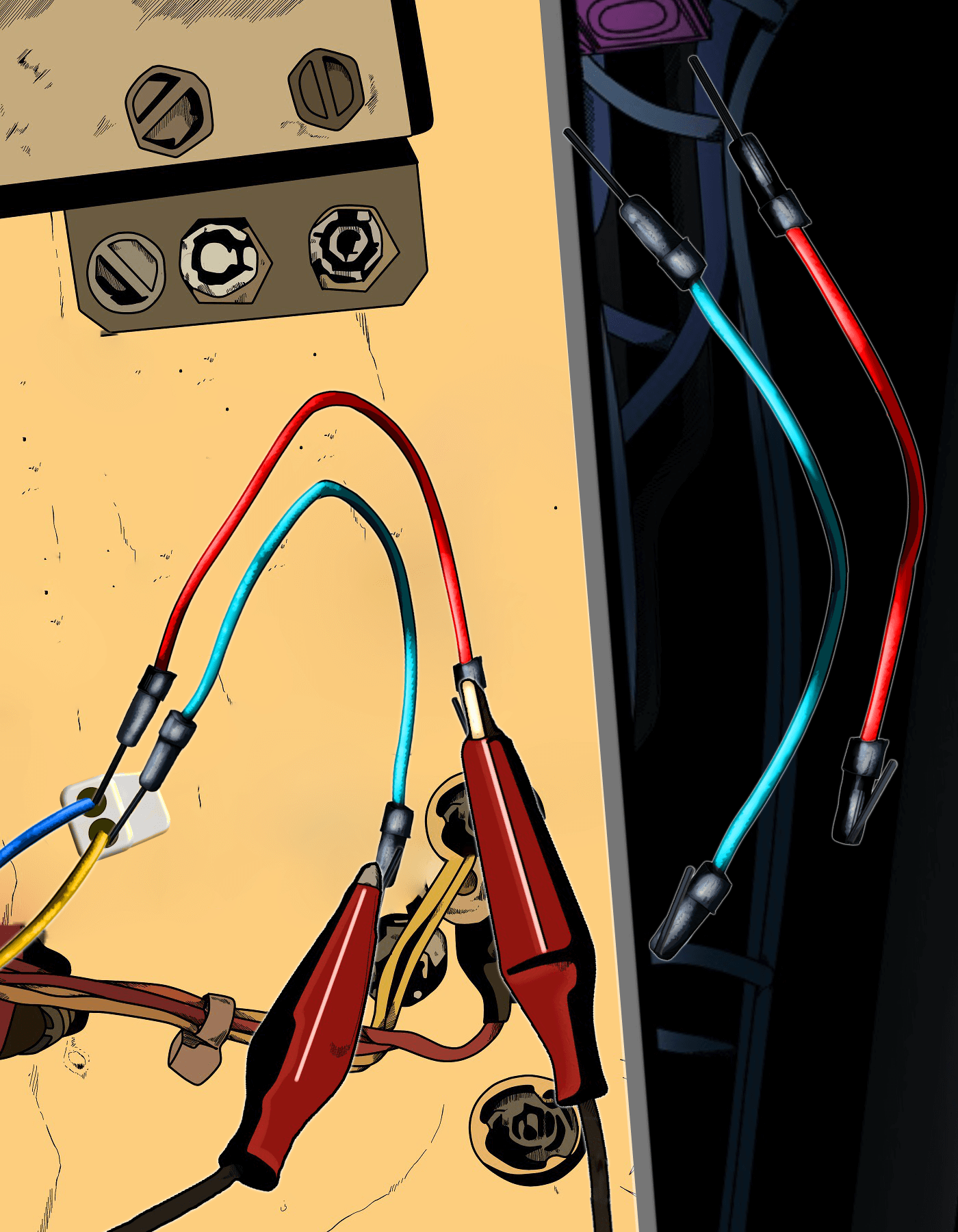
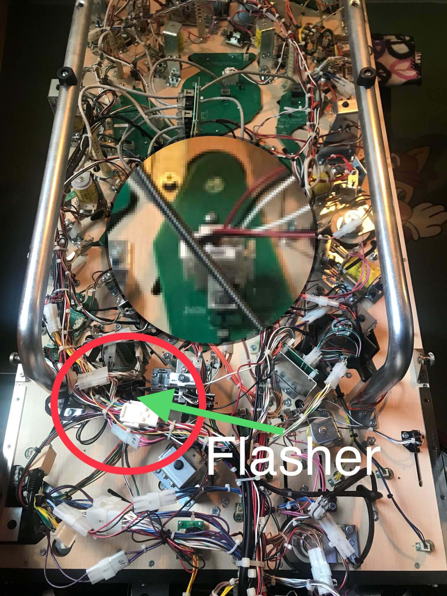
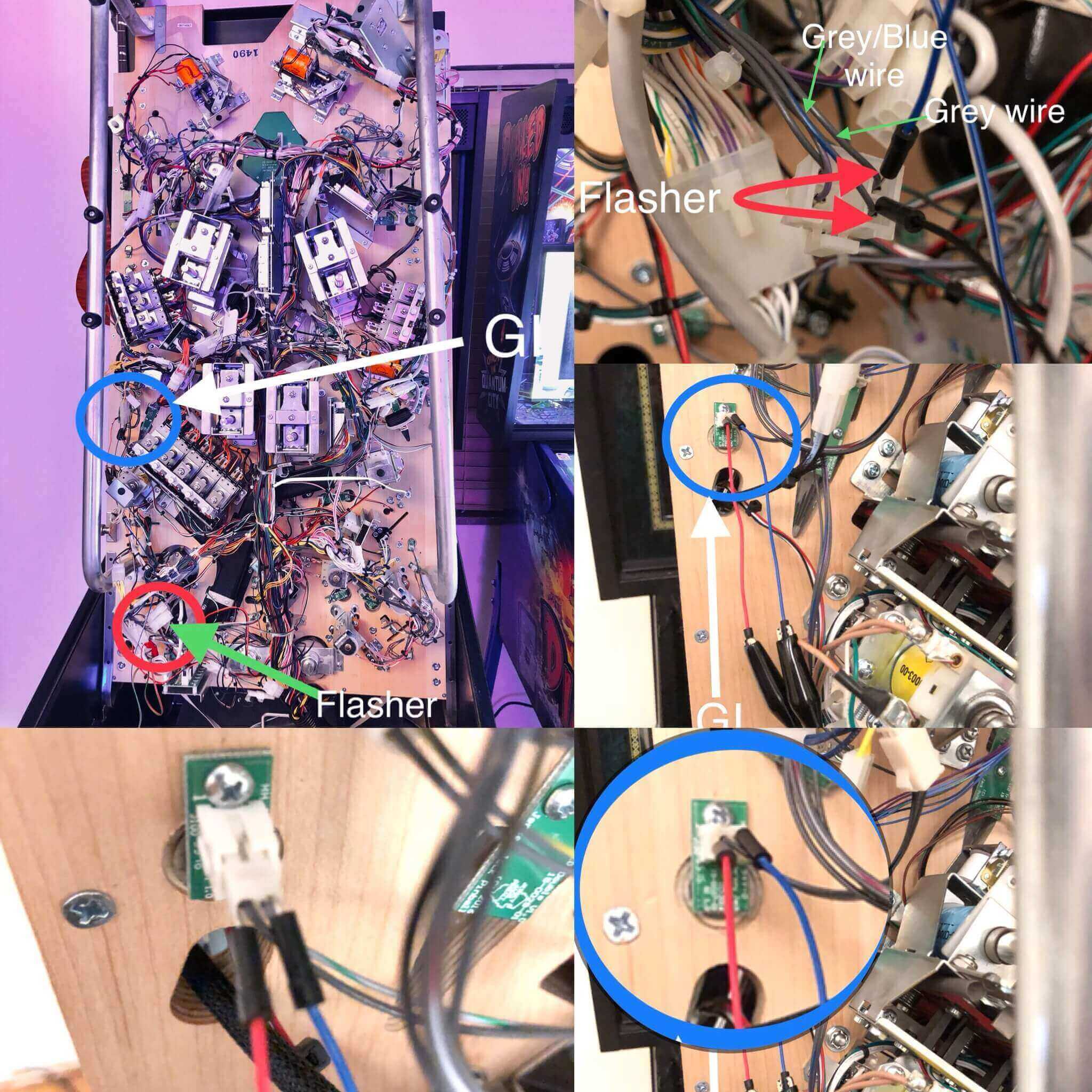
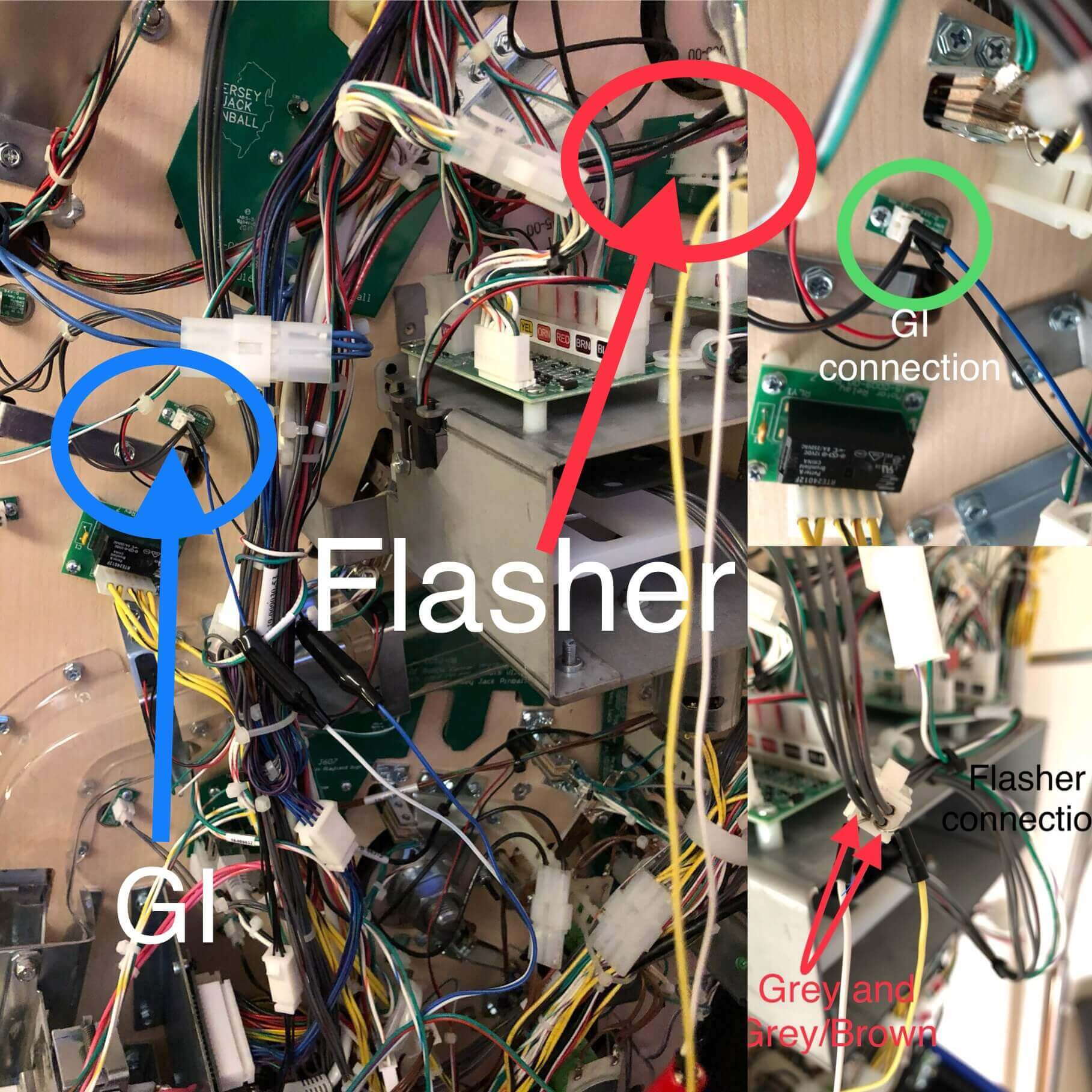
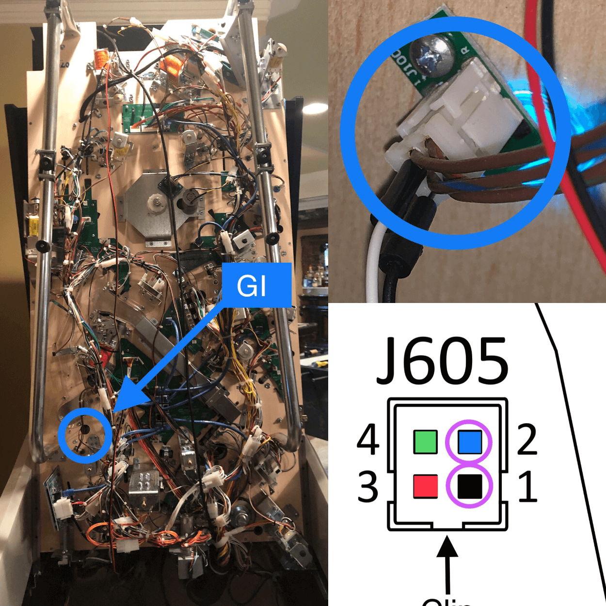
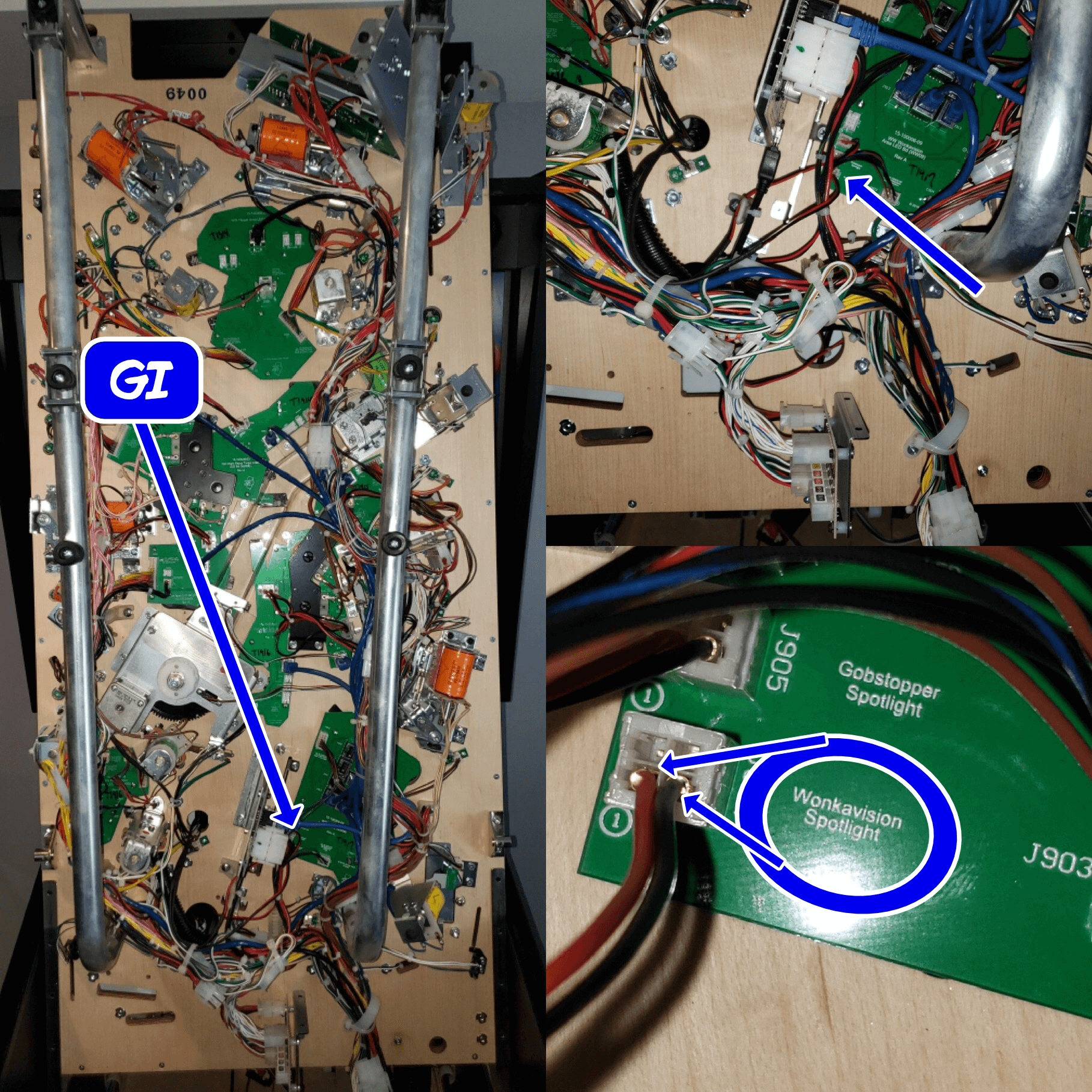
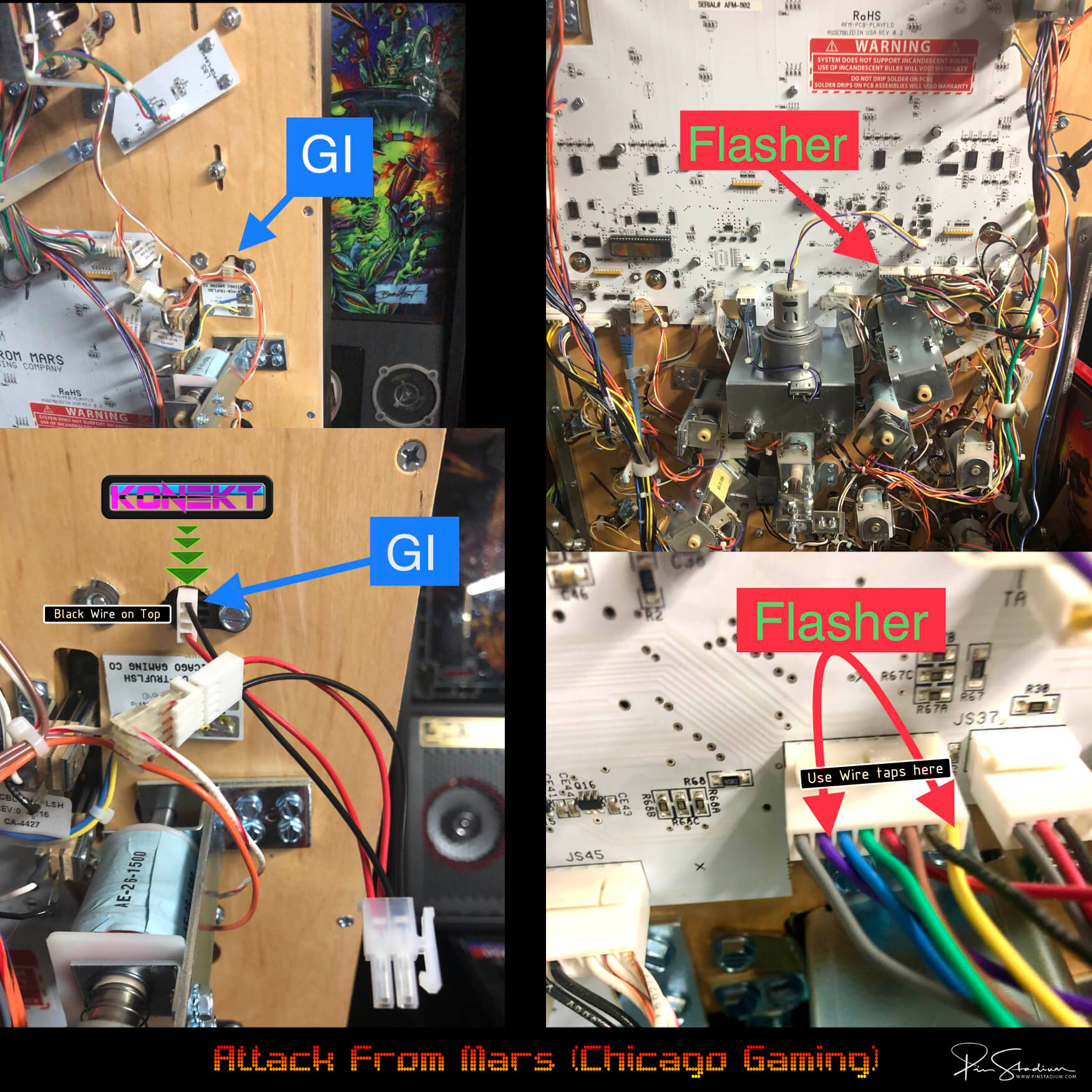
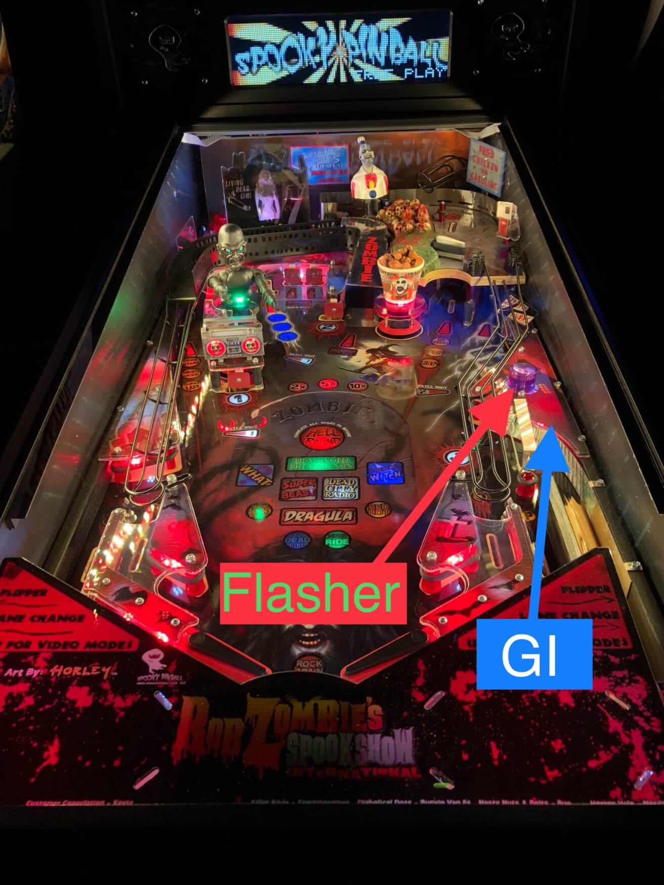
Most machines (Stern, Williams, Bally, etc.)
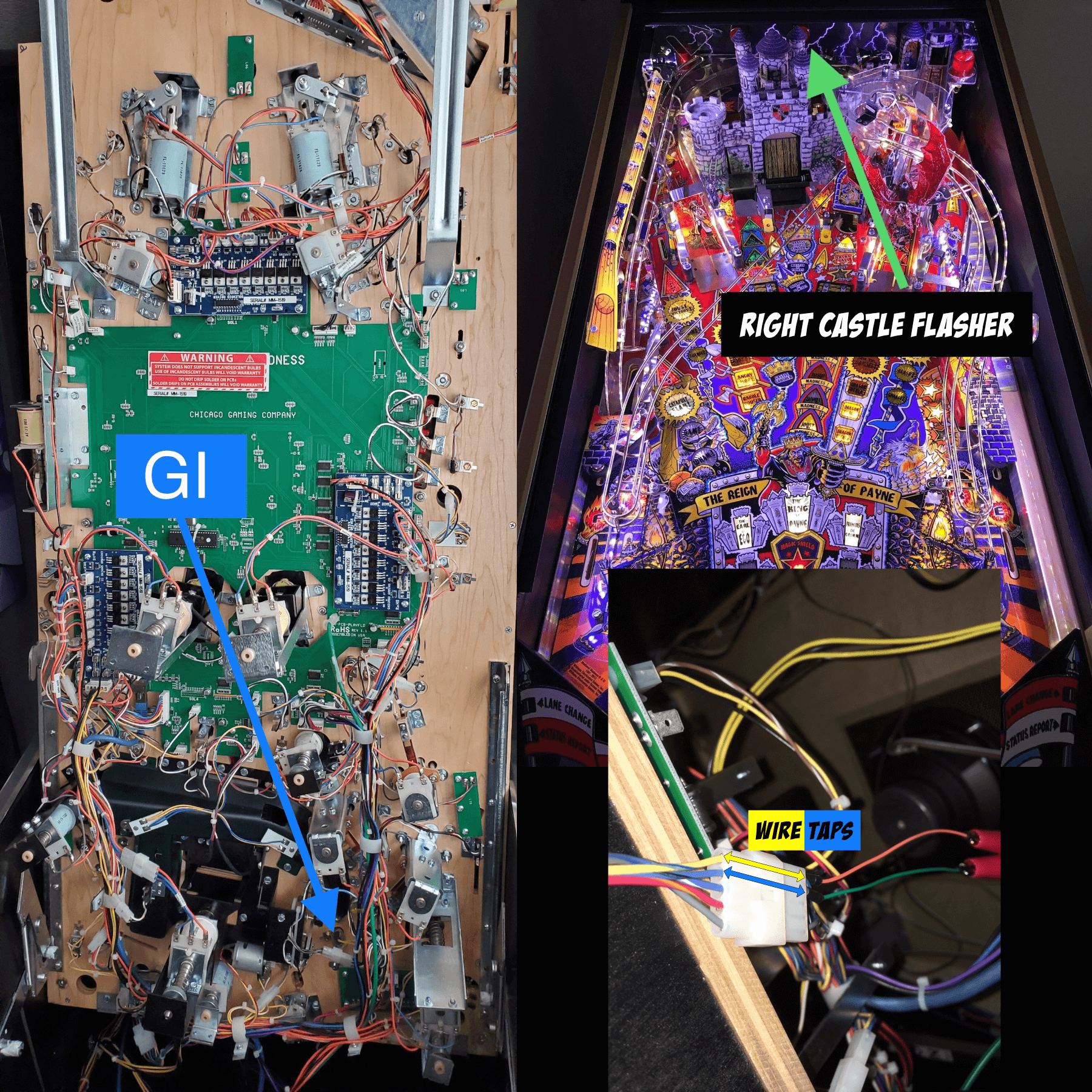
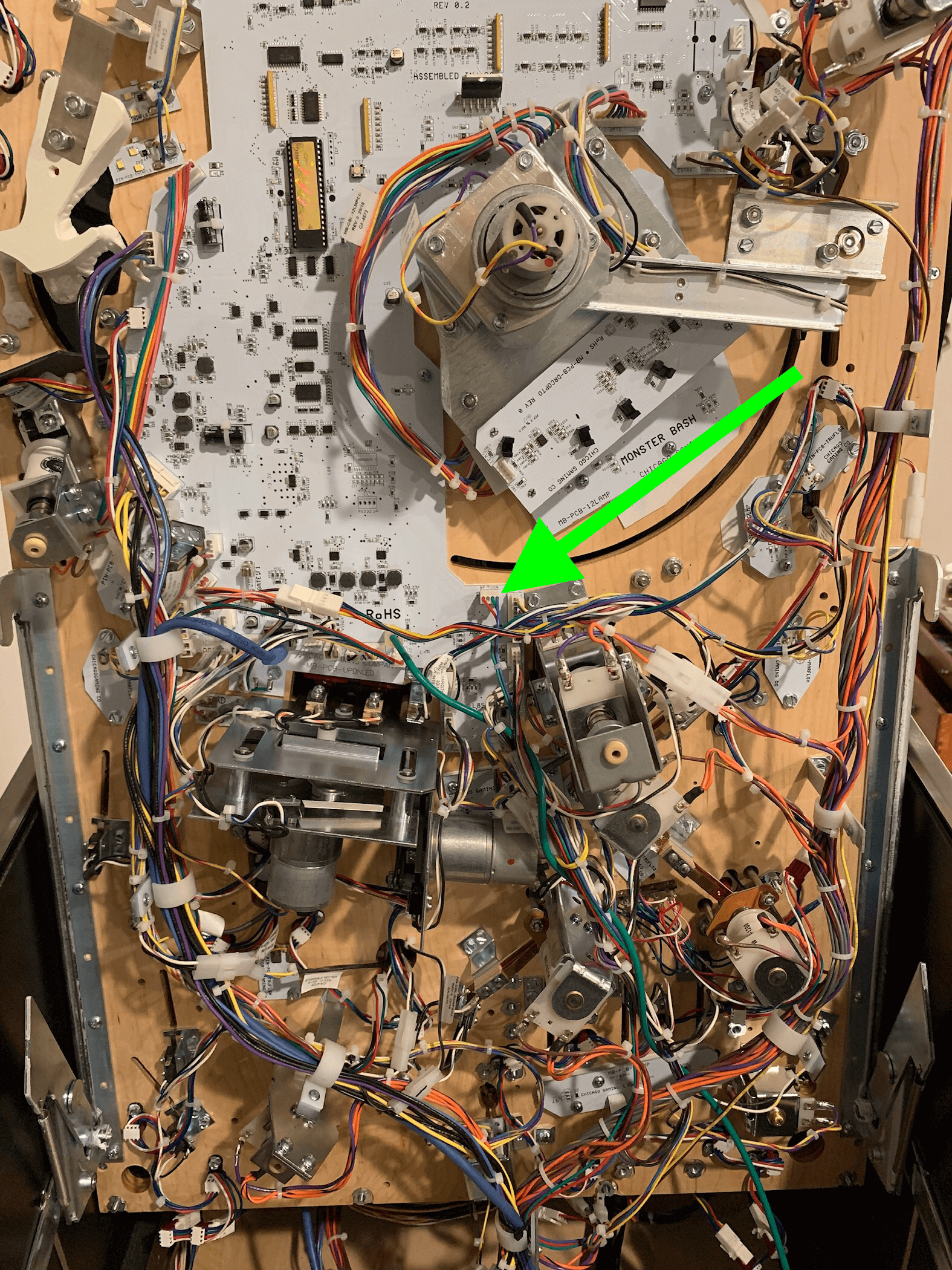
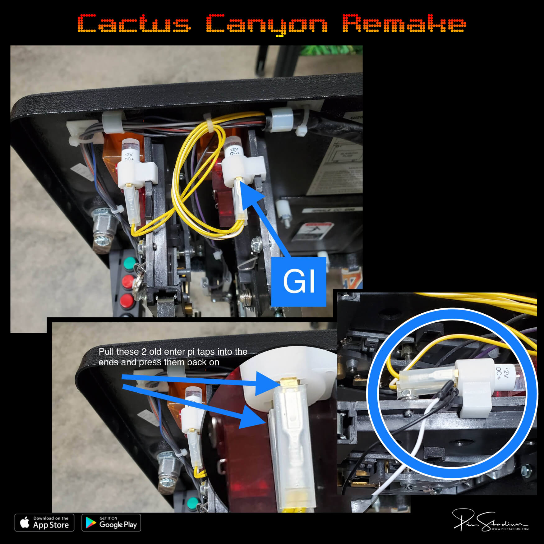
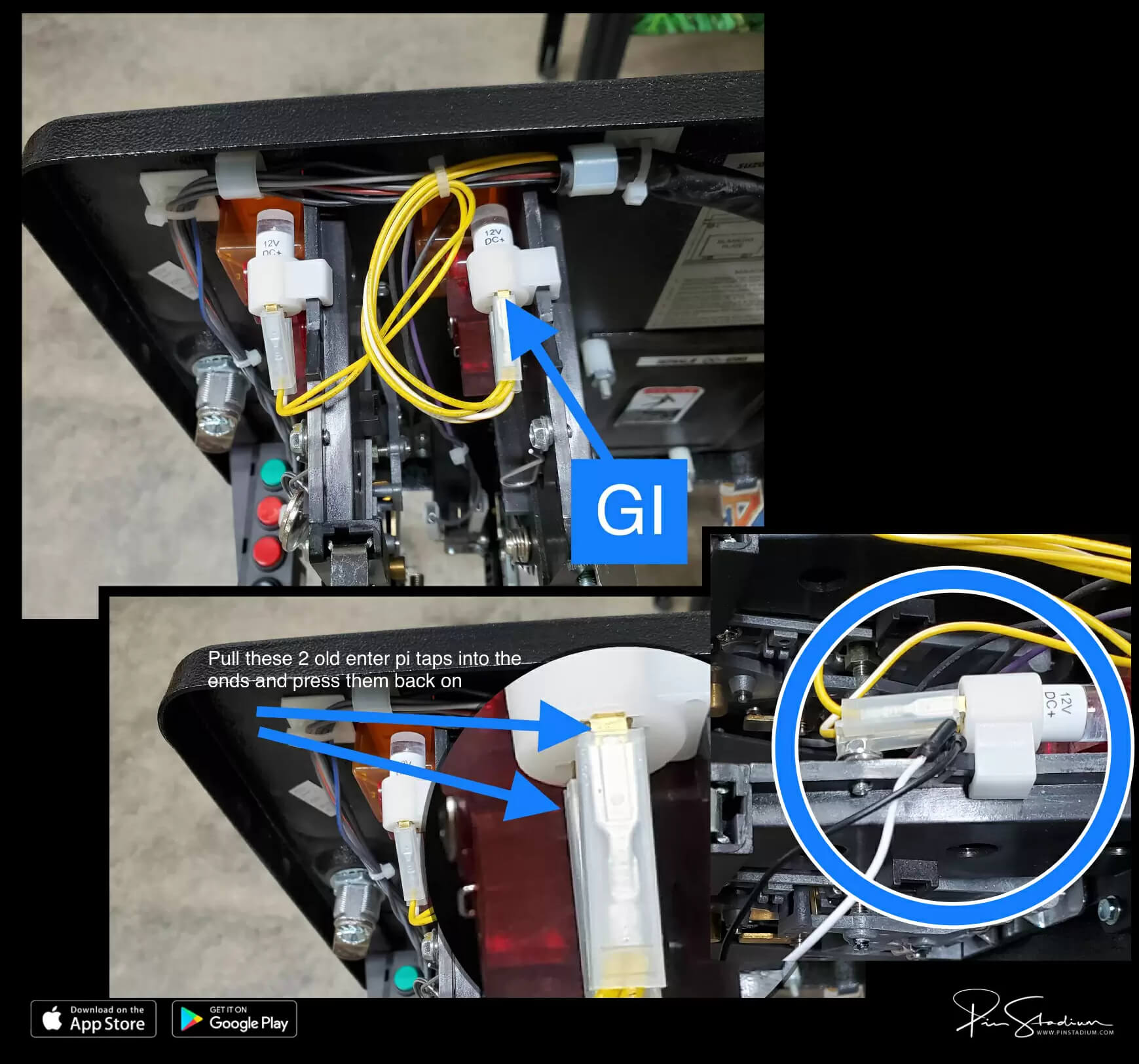
GI (Blue/White cable): clip the alligator clips onto any white GI bulb’s two leads. On most Sterns, look for a yellow wire — that’s GI. Polarity doesn’t matter.
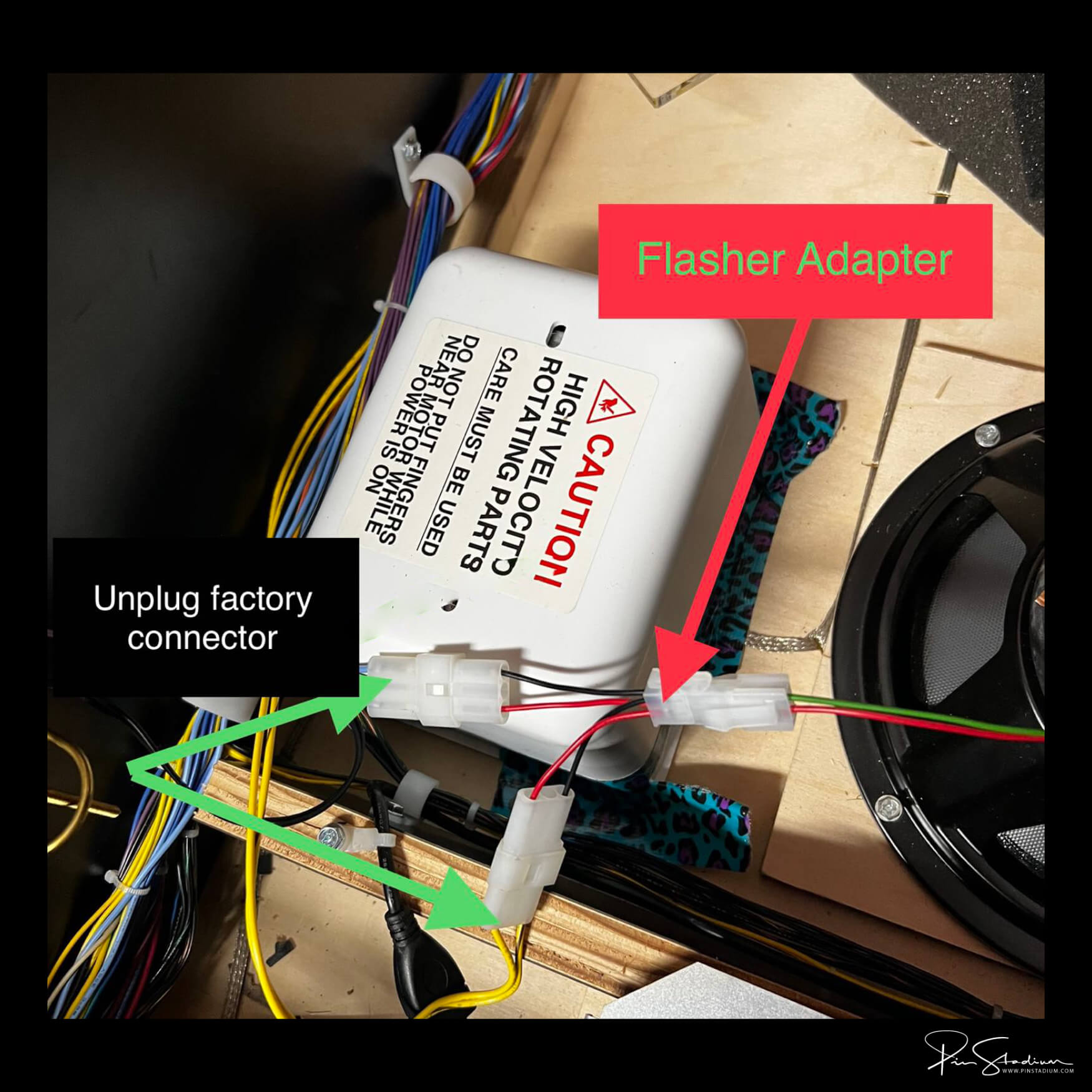
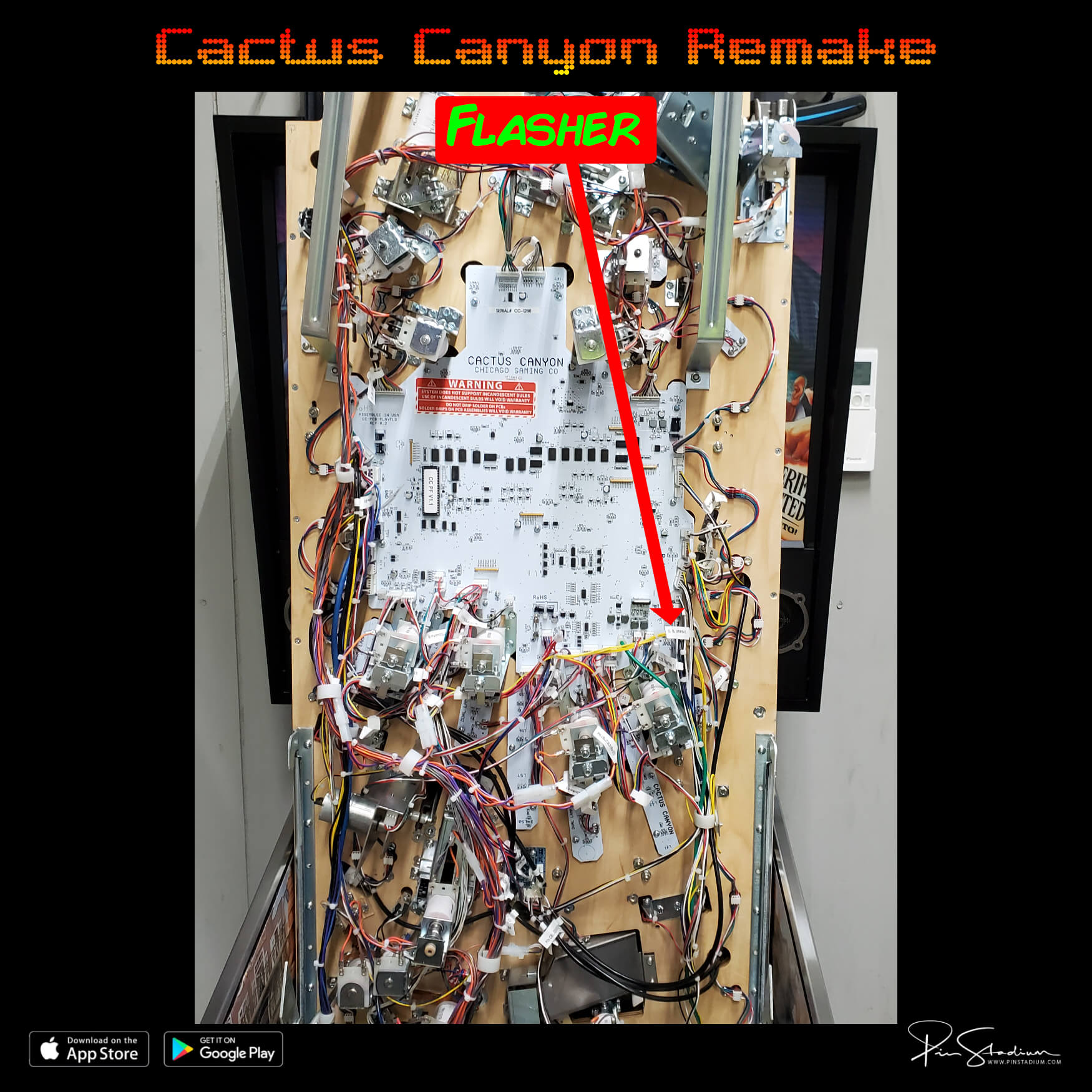
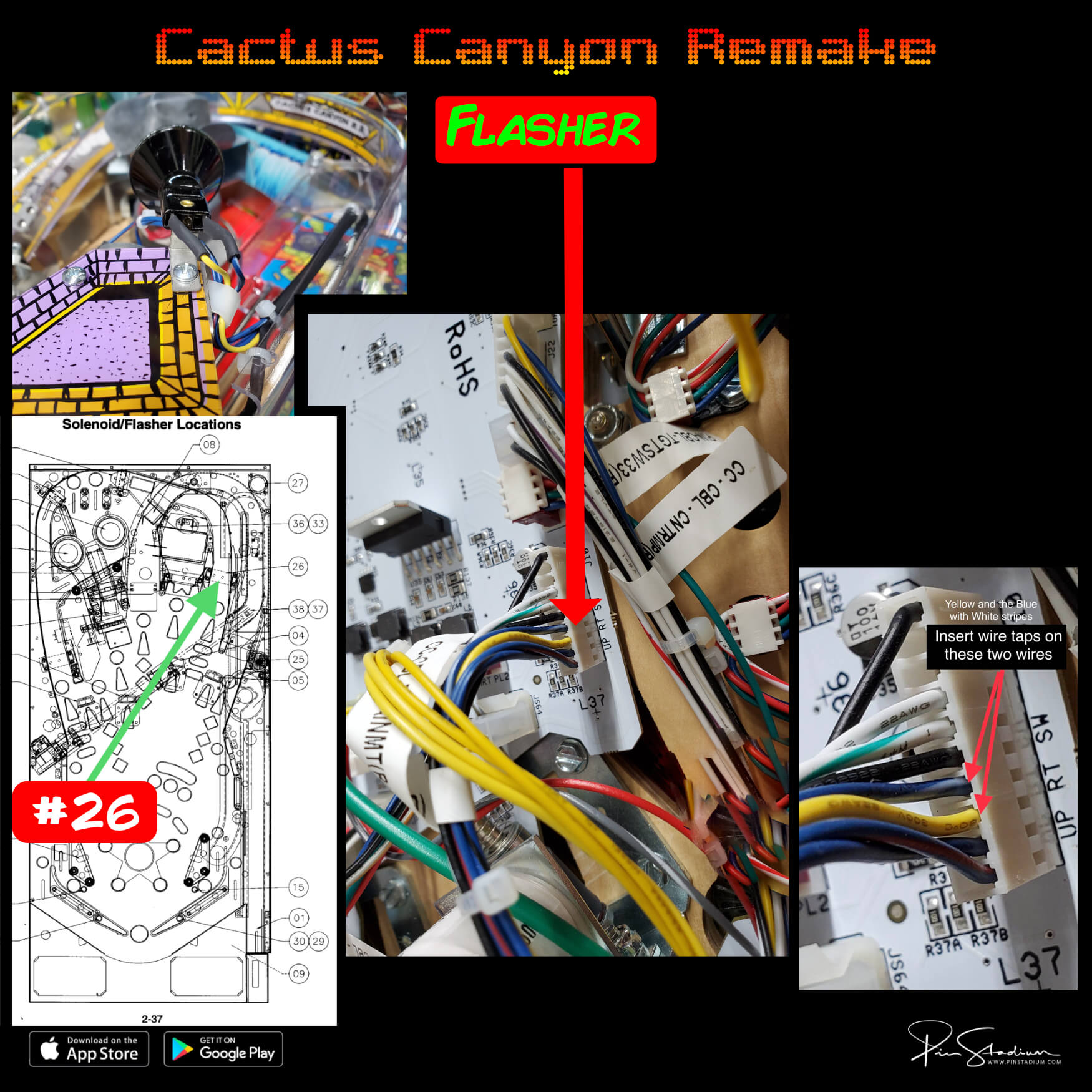
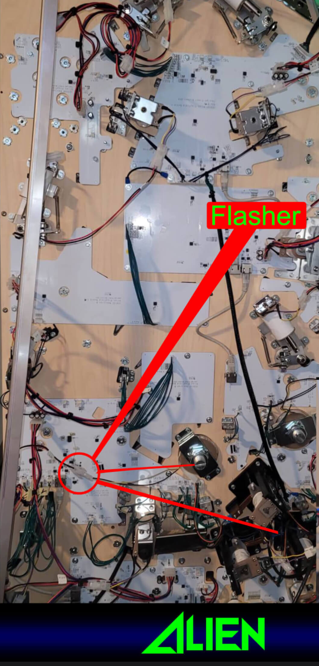
Flasher (Red/Green cable): connect to a real flasher (not GI). To find one that actually flashes:
- Open the coin door and pull out the white interlock switch (this enables flashers in service mode).
- Go to Settings → Diag → Lamps → Flash.
- Cycle through flashers with the volume or flipper buttons — the screen shows the flasher number and the factory wire colors.
- To confirm, unplug the flasher’s connector at the bulb. The bulb should stop flashing. Reconnect and it flashes again. Now you know you have the right one.
For per-machine flasher pick recommendations → Specific Flasher Connections by Machine
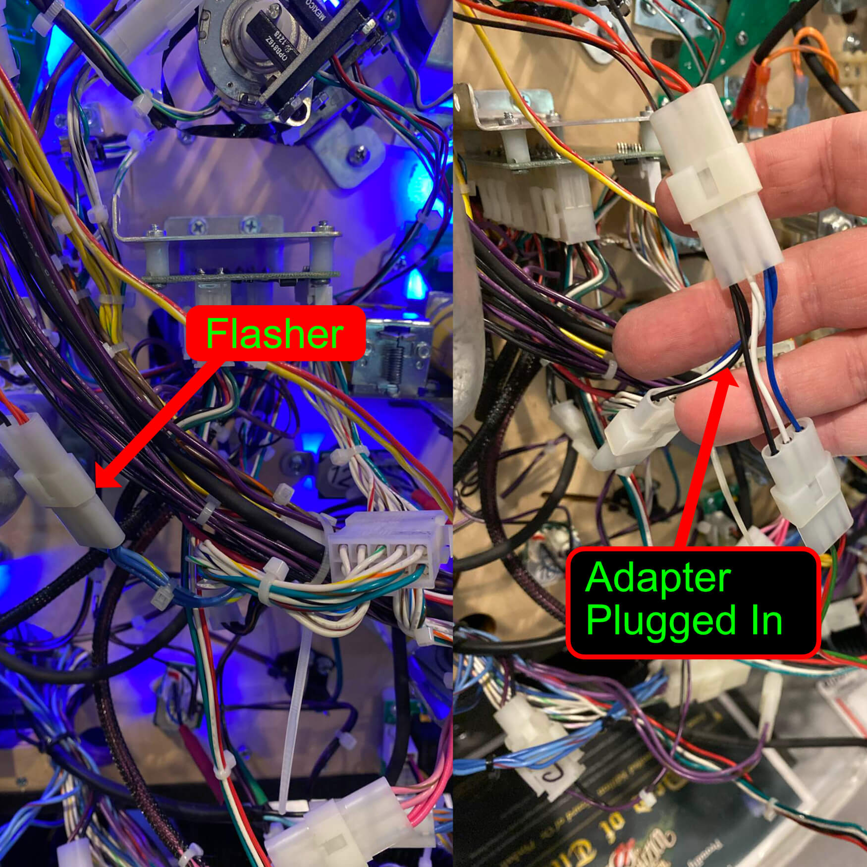
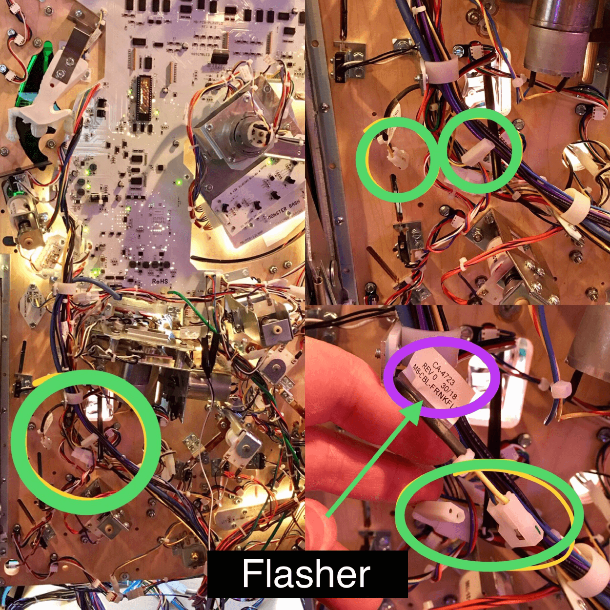
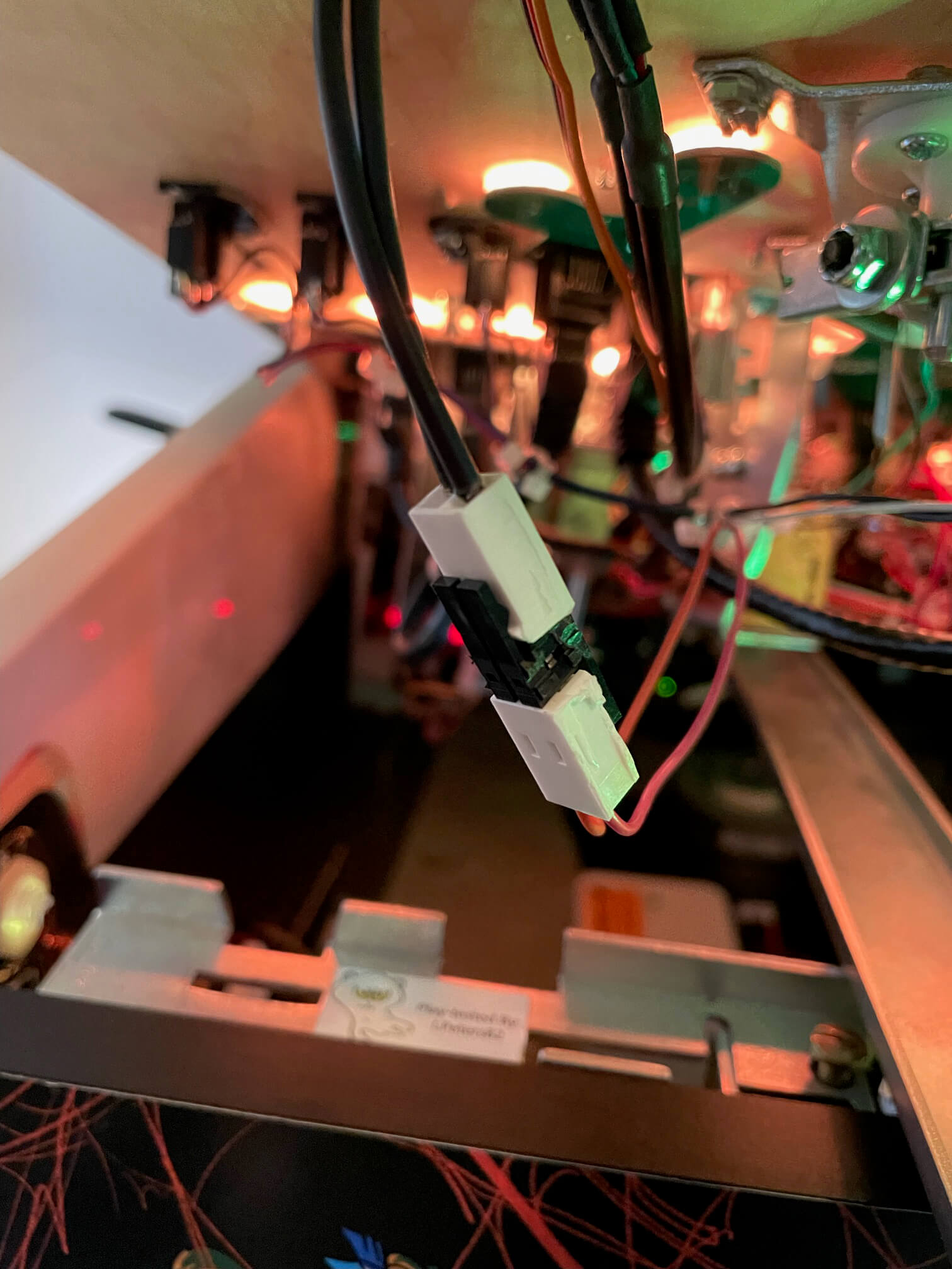
Alligator clip: fold the existing wire over the black barrel and clip on. For a semi-permanent setup, wrap with electrical tape.
Wire taps (small colored stiff wires with black barrel ends): pressure-fit into the back of a connector — useful when alligator clips can’t reach. Watch the wire-tap video →
Konekt adapter (if supplied with your kit): plug-and-play factory-style connector. No clips needed — plug it inline.
Permanent install: solder or splice into your chosen point.
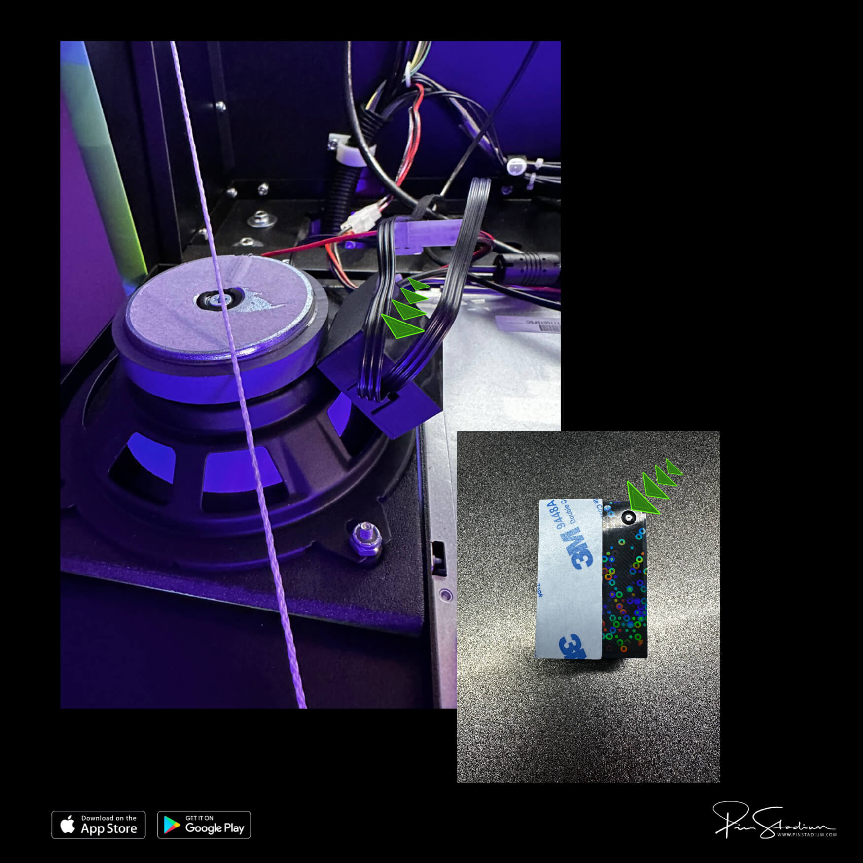
If you have the Neo “X” with Lumi-Motion, plug the supplied power splitter into the service port behind the right speaker on the backbox. Plug both power supplies into the splitter and run the cables into the bottom of the cabinet for later access.
Mount the Lumi-Motion module: remove the 3M backing and stick the module on the back of the speaker. The small port points down, into the speaker opening; the adhesive sits on the outside radius of the speaker.
The Lumi-Motion comes pre-programmed to sync automatically. Most users should leave it alone.
To customize (optional, for tinkerers):
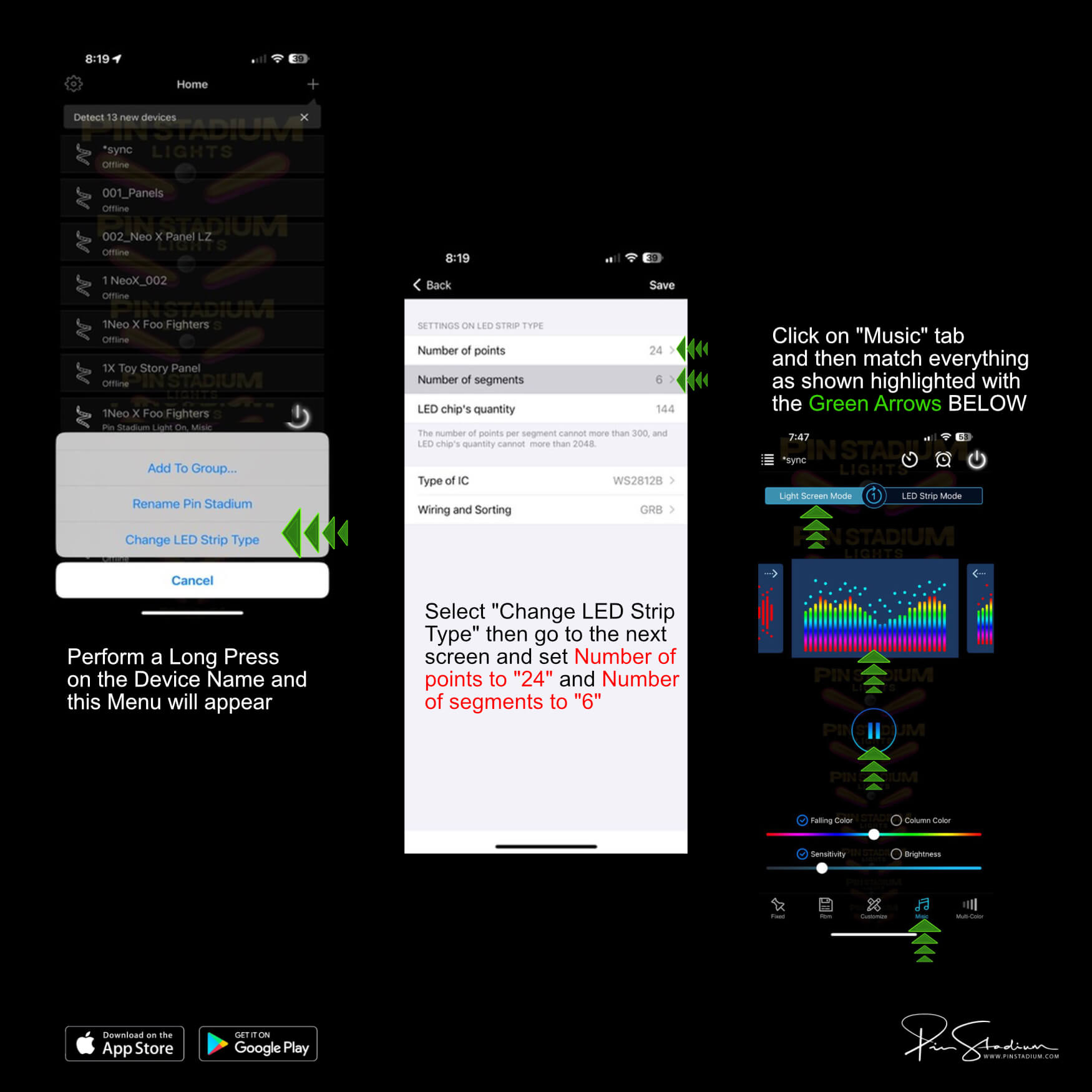
- Plug power into only the Lumi-Motion module (unplug your other Pin Stadium modules temporarily so you don’t get confused with multiple LEDNet networks).
- Wait 30–60 seconds for the “LedNet****” Wi-Fi to appear.
- In the Pin Stadium app, add it as a new device. Label it something obvious like “game name Lumi”.
- Long-press the device → Change LED Strip Type → match the values shown below → Save.
- Go to Music tab → Device Microphone → Play → Light Screen Mode → pick the first colorful spectrum option.
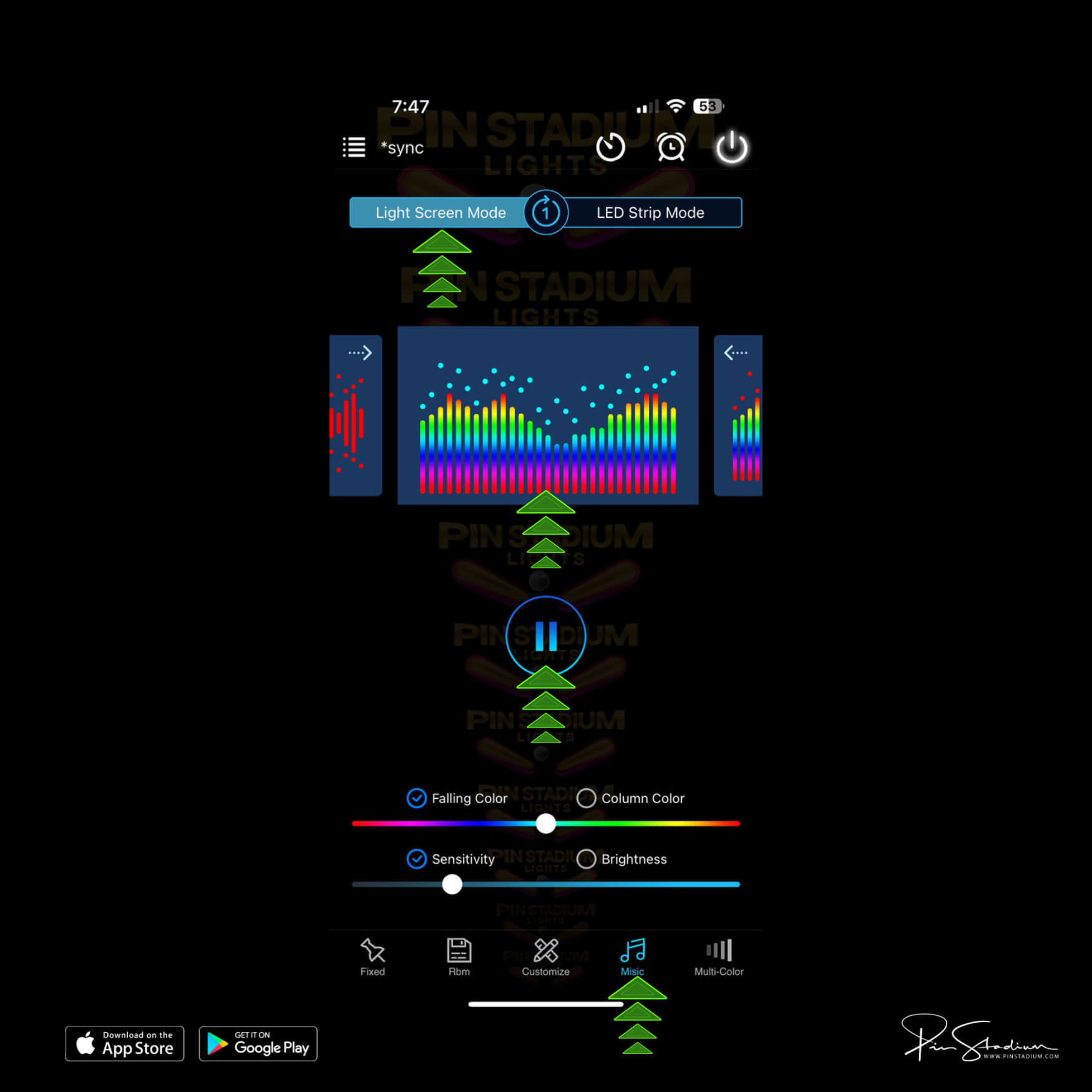
Adjust brightness and sensitivity to taste. Default is 5% — turn it down from there, not up. The Lumi-Motion is designed for live motion effects, not main playfield illumination — that’s what the GI light bars are for.
Tip: plug your game into a switched outlet or power strip and turn it off that way. Otherwise the Lumi-Motion picks up ambient room sound while the game is off.
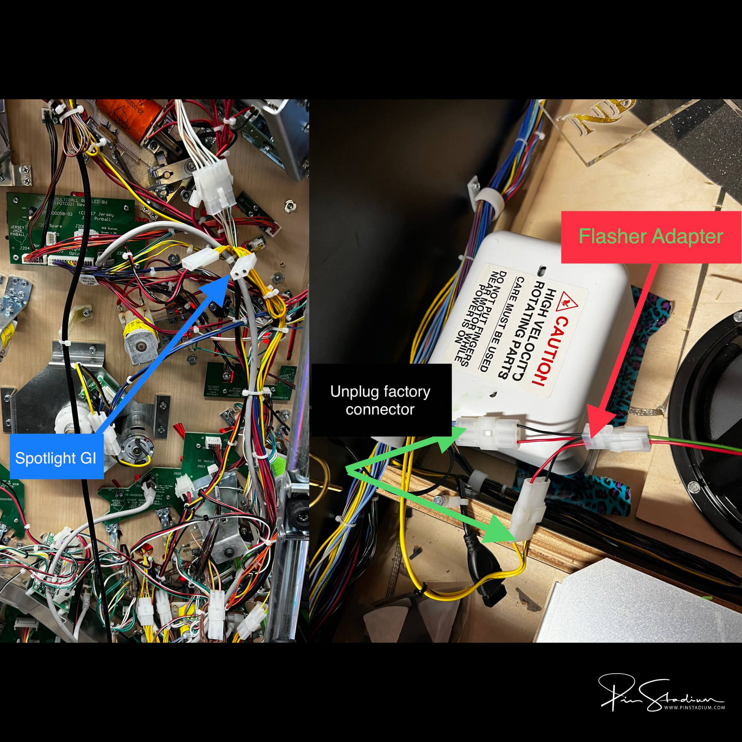
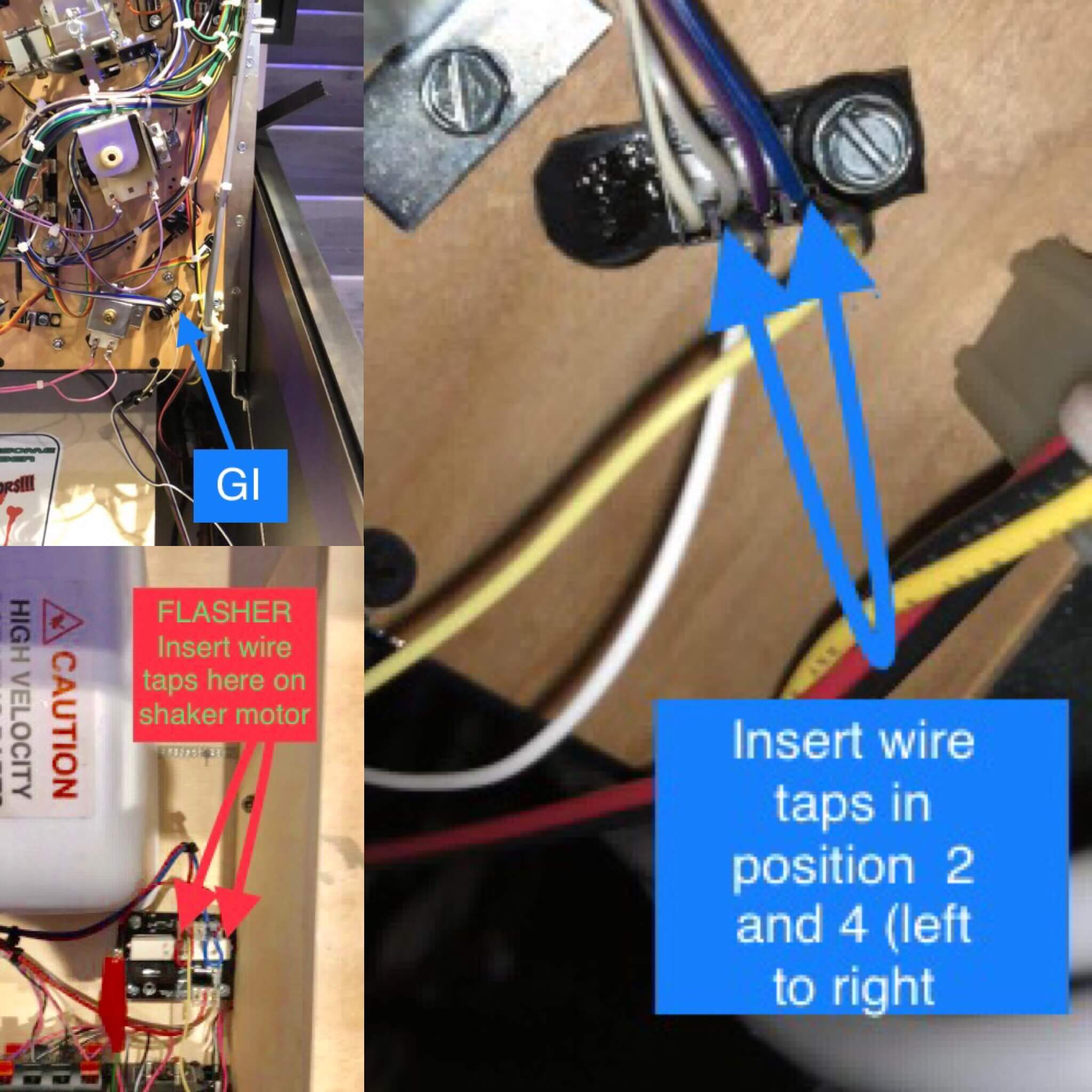
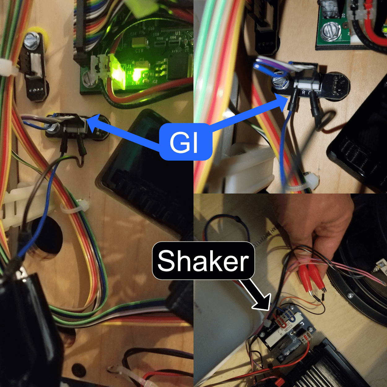
All American Pinball machines
Preferred: trigger both GI and Flasher from the backbox LED strip (wire-tap both wires). See diagram
Alternate GI: coin door slot bulb.
Dutch Pinball — The Big Lebowski
Power & GI: See the Pinside thread.
Flasher: none, unless you want to solder directly to a resistor on the board.
Step 2
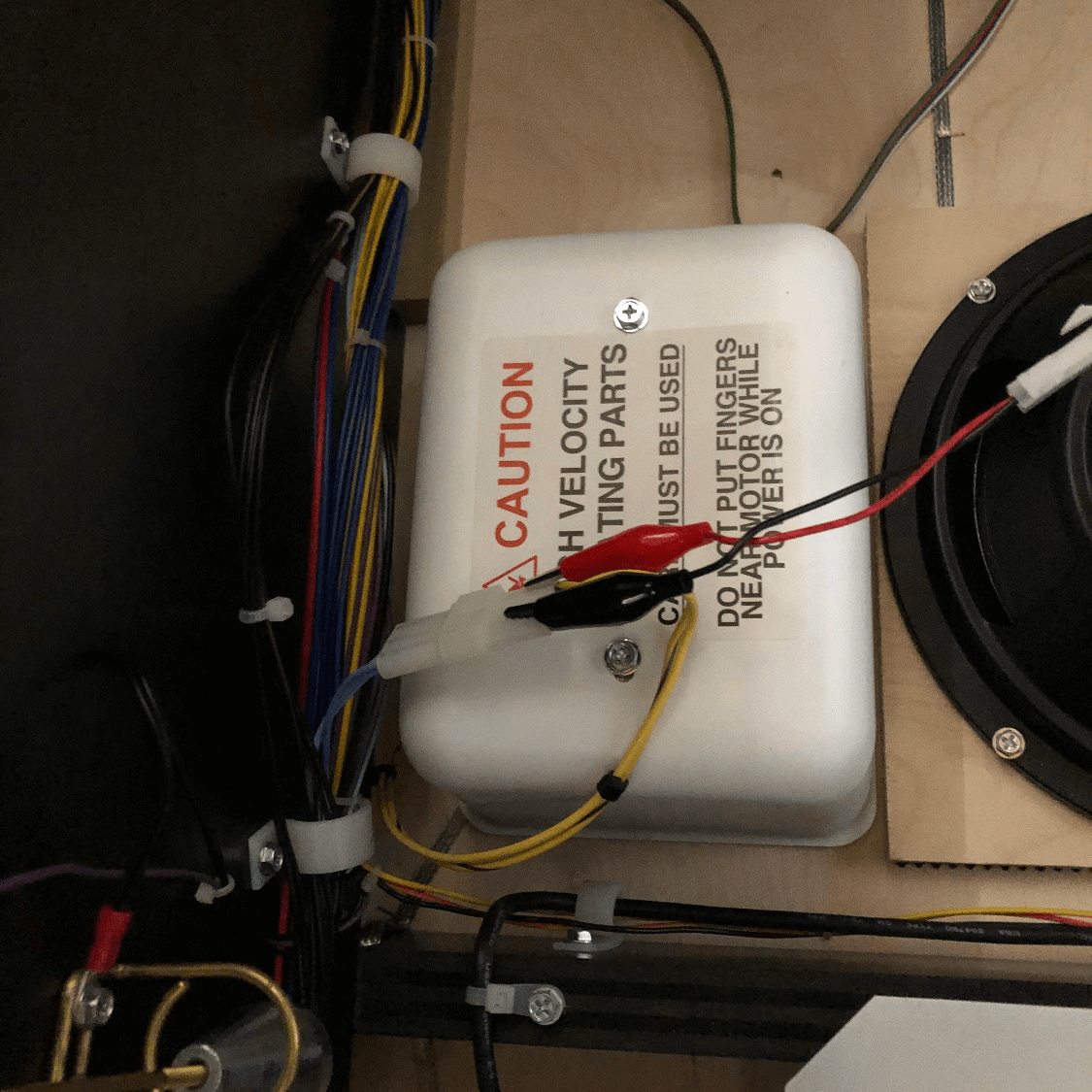
Plug in the Universal Power supply
Plug the Universal Power (shown below) into your machine’s service port. On most machines it’s in the bottom of the cabinet near the coin door (usually to the right). On newer Sterns (Spike 1 / Spike 2) it’s behind the translite on the lower right. The plug looks like a standard wall outlet.
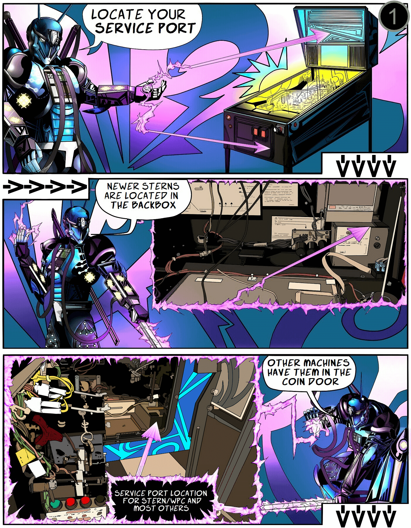
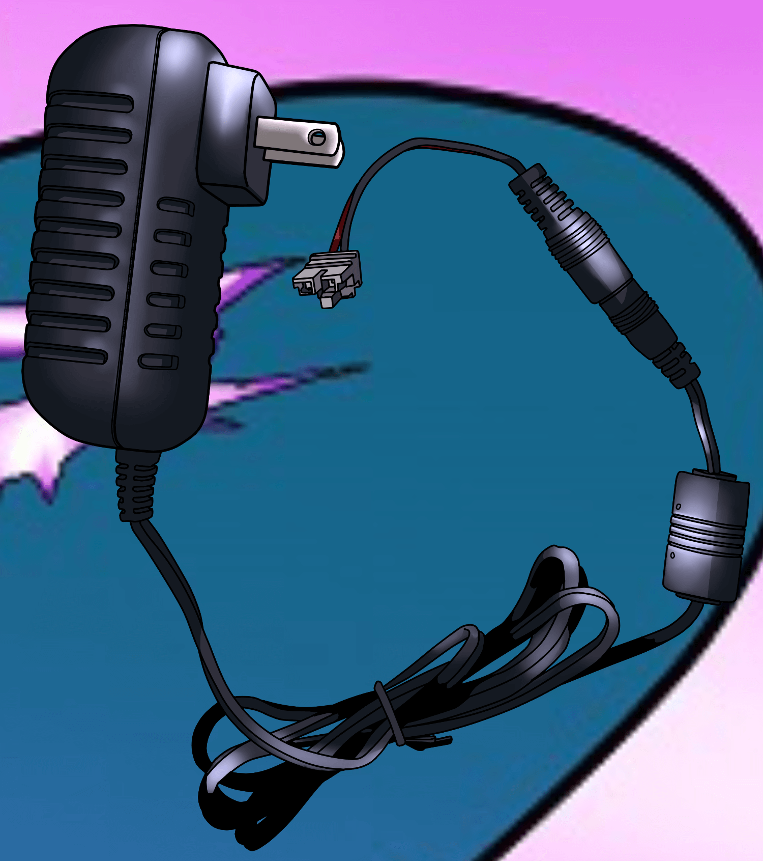
Older machines: some need a service-port adapter cable. If you listed your machine when ordering, we included one. Otherwise, grab one at our store or a local computer shop.
Step 3
Connect the cables to the Pin Stadium GI module
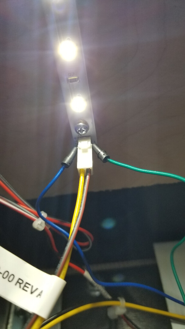
Lower the playfield back down to its resting angle and rest the light bars on top of the playfield. Now plug the power, GI cable, and Flasher cable into the Pin Stadium GI module as shown:
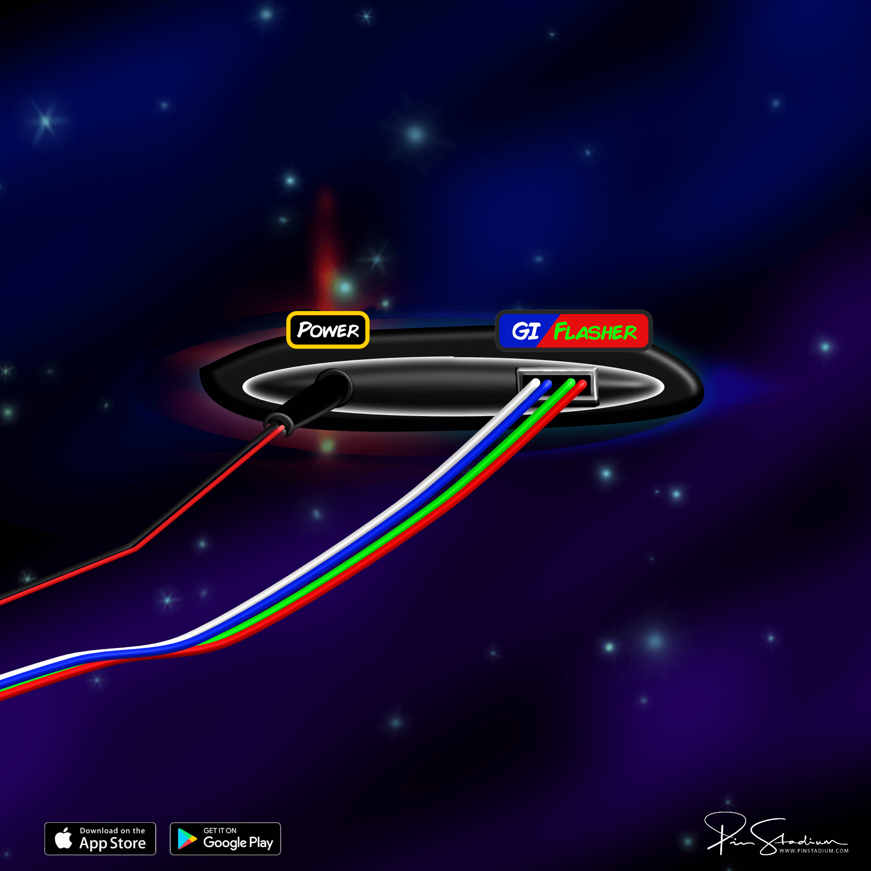
If your module uses a non-USB plug, use this diagram instead.
Step 4
Mount the ribbon-cable clamps and tuck the cables
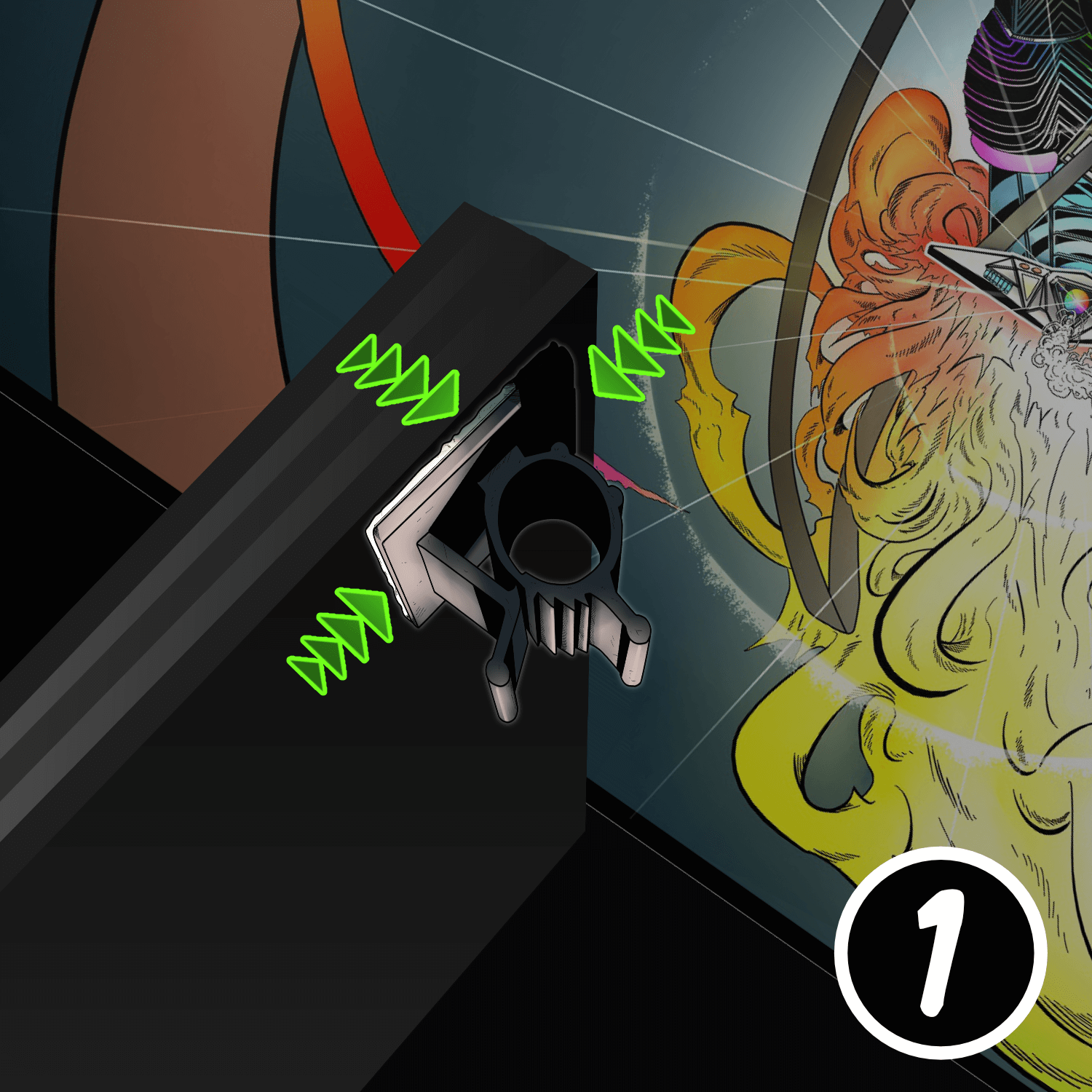
Place the connected GI module over the backboard, into the bottom of the cabinet, out of the way of any moving parts.
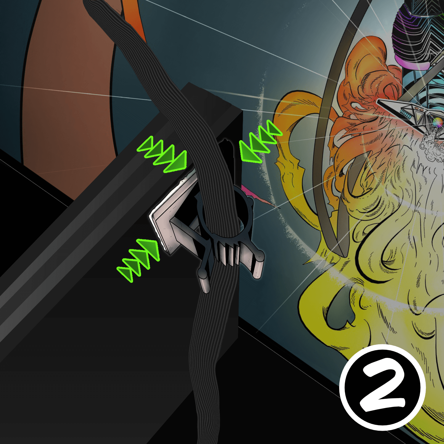
Find the small adhesive ribbon-cable clamps in the accessory packet. Stick one to the upper-left and one to the upper-right corner of the back of the playfield (the backboard side). These clamps guide the ribbon cables and prevent them from getting pinched.
Pro tip: fold the ribbon cable in half lengthwise — it slides into the clamp easier and tucks away cleaner. Leave about 6–8 inches of cable between the clamp and the back of the light bar, with about 1 inch of slack. Too much or too little will cause problems.
Step 5
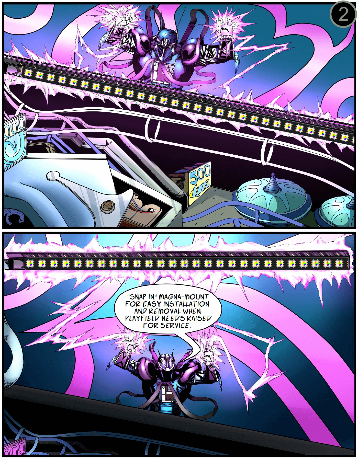
Prep the cabinet walls (and install Xeno Mounts first, if you have them)
Lower the playfield to its level resting position. Use the included alcohol wipe to clean the cabinet wall just below the playfield-glass track — about 2 inches down. It must be completely dry and dust-free for the Magna-Mounts to bond properly.
Position the lights 1/16″ below the glass channel, far enough back to hide the ribbon cable and clear the backbox hinge. The ribbon cable should tuck behind the back playfield-glass receiver channel.

Step 6
Peel, press, repeat
Carefully peel off the white protective backing on the Magna-Mount. Align the lights 1/16″ below the channel, far enough back to hide the ribbon cable and clear the backbox hinge.
Press firmly along the entire length of the light channel to maximize adhesion. Then repeat for the opposite side.
Take your time here — a sloppy bond means the lights will sag or fall.
Step 7 (Finished)
You’re done — light it up
Raise the playfield back to play position and replace the balls. Attach the light bars to their Magna-Mount backs on the cabinet sides, then replace the glass and lockbar.
Next: download the app and customize your lights
Enjoy the new look. Post a “before / after” of your machine (lights off vs. lights on, in the dark) on the Pin Stadium Pinside thread — we love seeing them.
Questions? Email me directly: Contact Pin Stadium
