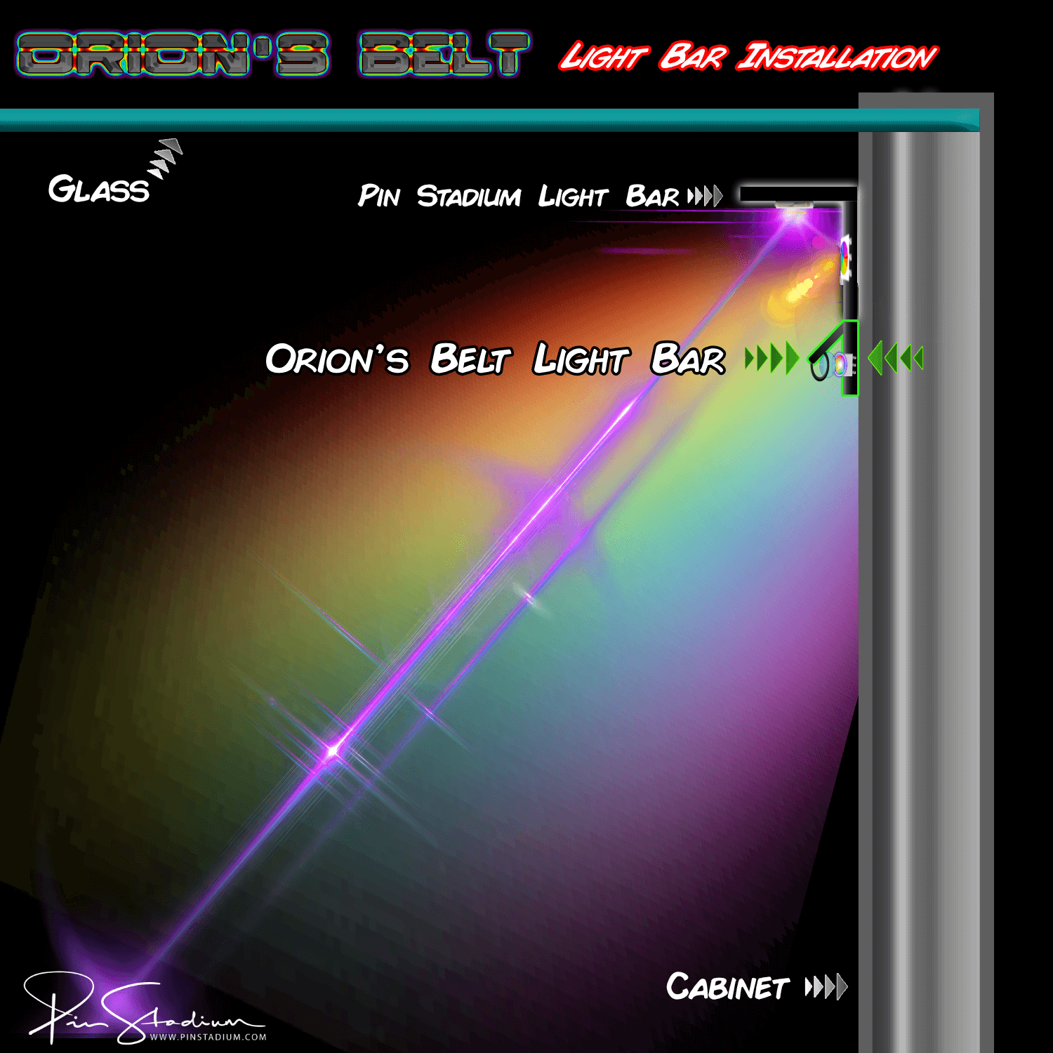
Quick start — Neo “X” Fusion Atom install
Time to install: 20–30 minutes (the Fusion does two installs — GI light bars first, then a second flasher bar set).

How this install works: the Fusion is two stacked installs in one kit. Steps 1–7 install the main GI light bars (same as a Neo Atom install). Steps 8–14 install a second, parallel set of Fusion flasher light bars that ride alongside the GI bars and pulse in sync with your machine’s flashers.
⚠ Three things you MUST know before starting
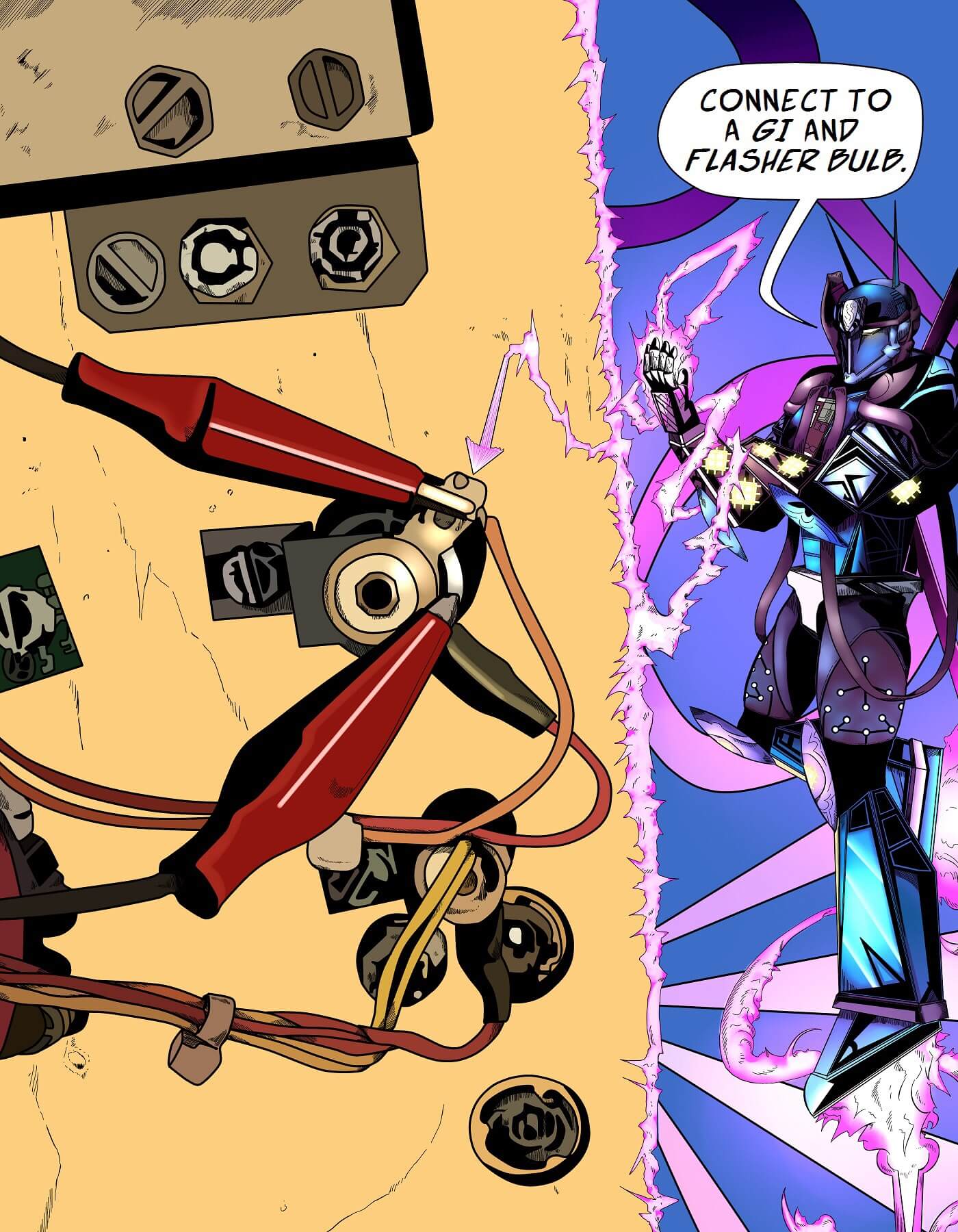
- Never connect the Red/Green flasher cable to a GI bulb. The light bars will overheat and warp.
- Some “flashers” don’t actually flash — they’re on more than they’re off. Don’t trigger from those either.
- Install at your own risk. If you’re not comfortable inside your pinball machine, ask a knowledgeable friend or technician.
Installing the standard (non-Fusion) Neo Atom? Use the Neo Atom install guide instead.
Already know the basics? Skip to Specific Fusion Flasher Connections by Machine.
If you’re unsure about anything, email us before connecting. We’d rather help you up front than have a damaged module to deal with.
Step 1
Raise the playfield and identify your two connection points
Remove the playfield glass and balls, then raise the playfield to its vertical service position.
You’ll connect two cables from the Pin Stadium harness:
- GI cable — Blue/White → any white GI bulb (always on during play). Polarity doesn’t matter.
- Flasher cable — Red/Green (UV+Glow) → a real flasher (briefly on during gameplay events). Polarity doesn’t matter.

Find your machine in the tabs below. Use the Standard tab for most pinballs (Stern, Williams, Bally). If your manufacturer is listed in another tab, use that instead.
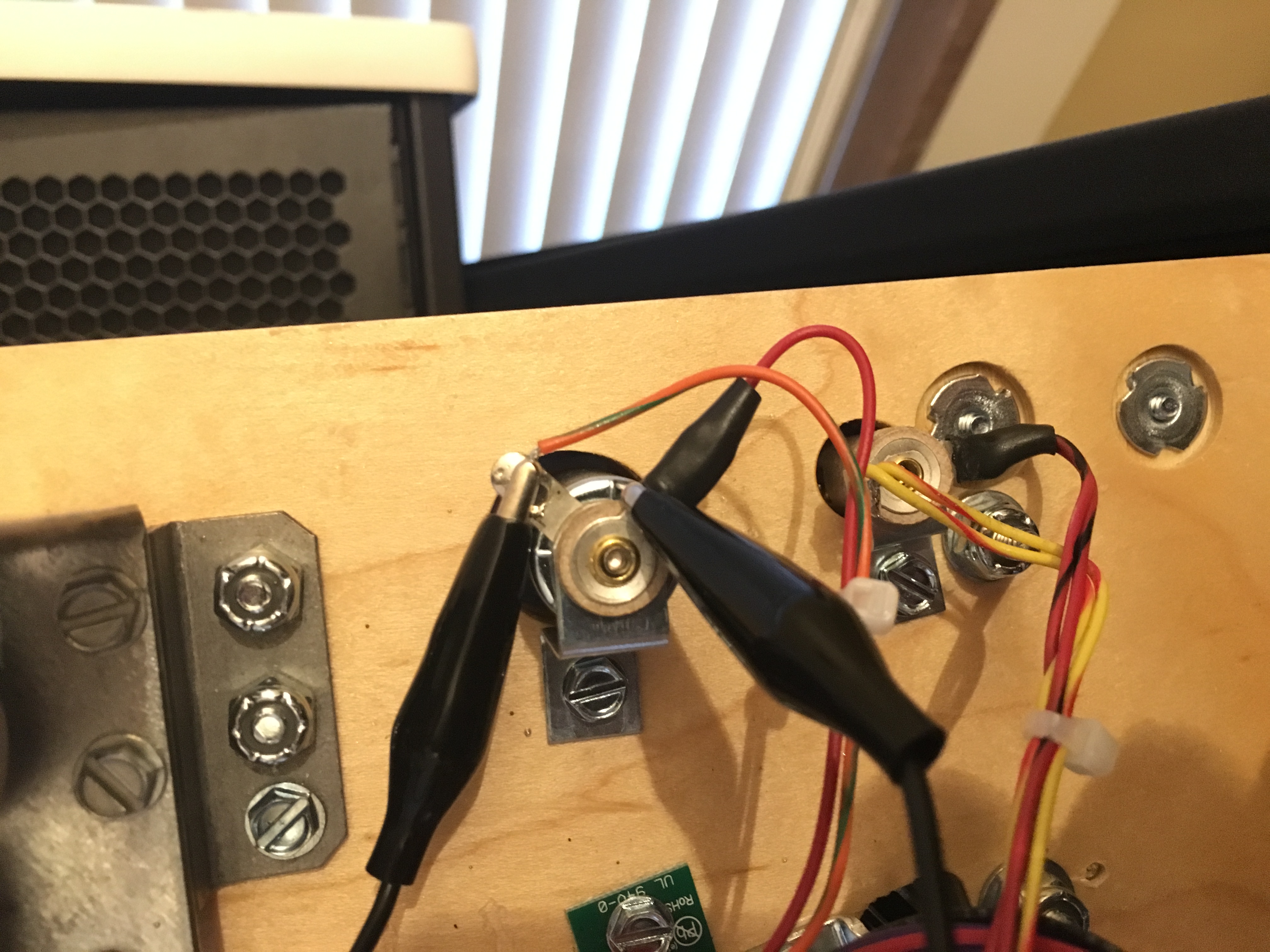
GI: Connect the BLUE/WHITE cable’s alligator clips to a GI Bulb (polarity is not important so it doesn’t matter which side you connect them to).
Flasher: Connect the RED/GREEN cable’s alligator clips (polarity does not matter here either). For specific flasher trigger locations for the Red/Green cable(UV+Glow) for your pinball machine you must CLICK HERE
Note: In some cases the alligator clips may not be able to reach into your desired location. If you are trying to connect to unreachable terminals then please use the wire tap leads lead (small colored stiff wires with black barrel ends). These are great for tapping in the back of a connector terminal or EVEN BETTER if your flasher connector looks like the one in this video then you can get an even more secure method to connect it. Check out our wire tap video here Optionally if you want a permanent installation then you can solder or wire splice into where you determine is the best location. Also if you see a connector other than an alligator clip, then this means that your have our new Konekt system (if available for your machine) which will allow you to connect to the recommended flasher or GI using a direct factory style plug and play connector to make things even easier. Find the flasher on your machine that matches the connection and you are good to go. Also make sure you connect to a flasher and NOT a GI bulb. If you mistakenly connect the flasher cable to a GI then the lights will get very warm and can damage the light bars or module. Also on some machines the flashers are labeled as such but they do not flash, but instead are “On” more than they are “Off” during gameplay or attract mode(when game is one but idle). Their “flash” function is when it is turned “Off”, which means you absolutely do not want to connect to these as it will damage the Orions Belt flashers or lights bars since they are not designed to be “On” like that. This is why it’s important to follow our guide and if you do not see your game listed, always send an email if you are unsure. So be sure to always follow the Specific Flasher Connections recommendations.
Here is how to locate the Flasher and GI:
———–
To find the flasher options(they are numbered) open the coin door and use the buttons to navigate to Settings/Diag/Lamps/Flash. You can then cycle through them (with the volume or flipper buttons) and get a visual locations of where they are located. The machine will also tell you what flasher# you are on too. This helps to makes things even easier using this method. You will need to pull out the white switch located near the hinge of the coin door to activate the high voltage for the flashers. Otherwise they will not flash then.
To help you trace and identify the 2 wires coming from the flasher:
Normally on the Stern machines they are an orange and red wire in most cases. On the screen when you’re in settings it also tell you the factory wires next to the flasher # too. It will also tell you the color of the factory wires on the screen. That way you will know what you are looking for. You can also confirm that you have the correct flasher by unplugging the flasher connection and the flasher bulb on the machine will turn “Off” and then plug it back together and the bulb will flash “On”. This way you will know 100% for sure you’re on the correct one and it is a flasher. Also “never” trigger from a shaker motor on a Stern machine, and only if you are instructed on machines like Jersey Jack Pinball machines, etc.
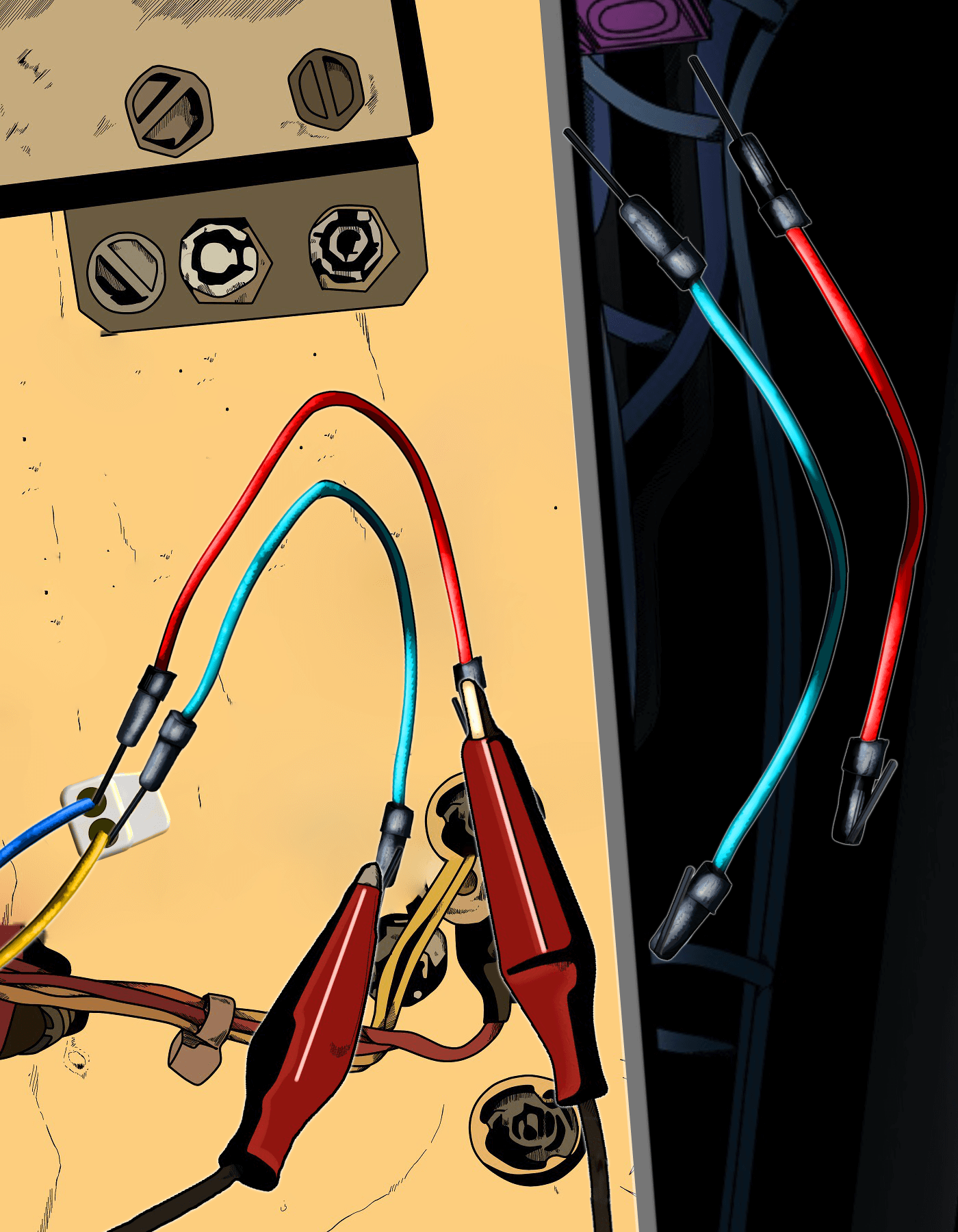
The Red/Green cable is the UV+Glow, if you are installing Fusions then it will alway have a black cable with a paired colored wire(Red,Green, or Blue etc). Then from that point you can plug in the flasher connection.
As far as the G.I. trigger:
Any white G.I. bulb for the Blue and White cable you can find will be fine. Generally on the Sterns it will have a yellow wire going to it to help you identify that. Just make sure it’s White and not any other colors as it will cause undesirable effects if it’s not White
———–
Play a few games and see which one you would like to connect to or Email Us if you are unsure.
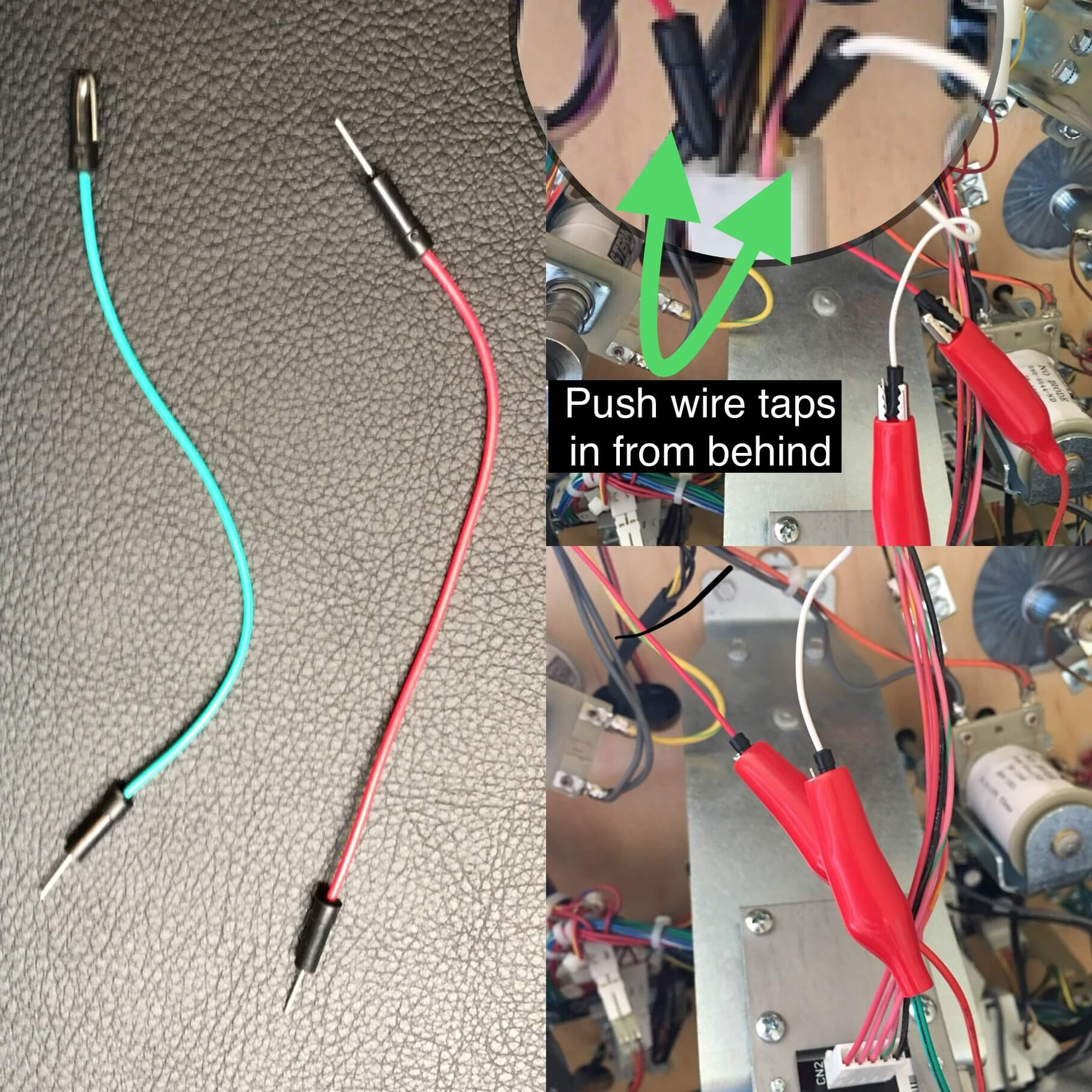
On the opposite end that you plan to clip to, simply fold it over the black barrel so that it has enough width to connect the clip over it. These methods of connection are generally used and can be semi-permanent solutions if done correctly and it is suggested to put some electrical tape over the ends of the alligator clips to keep them insulated when using the wire tap method. Optionally if you want a permanent installation then you can solder or wire splice into where you determine is the best location. With some installations you may be provided with wire taps built into the adapter and no alligator clip is needed.
Wire tap method shown here:
This next step is for NEO “X” ONLY!!! If you DON’T HAVE Neo “X” and just have regular Neo Atoms just skip to the next step after this
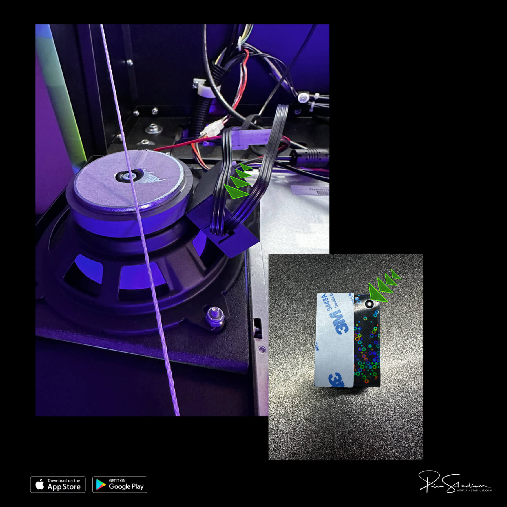
If you have the Neo “X” with the Lumi-Motion then you will simply plug in the power “splitter”(if you were supplied one) into the service port located behind the right speaker on the backbox. Plug the power supplies into the splitter and running the cables into the bottom of your cabinet so you can access them later. The 3m adhesive backing will be on the side that faces into the speaker area. Simply remove the 3m backing off and mount the Lumi-Motion wireless sensor box on the back of the speaker as shown. Make sure the small port is pointing down in the opening of the speaker and the adhesive is on the edge of the outside radius of the speaker:
Then plug the power from one of the power cables into the black box(has a patterned holographic design on it). It is best to have only the power going into this Lumi-Motion module for this step, otherwise you are going to get confused and see 3x “LEDNet***” Device showing up to connect to. If you don’t do this you will get confused and frustrated wondering which module is which. It’s always a good idea to connect to each module this way regardless, as it saves a lot of time. Once you do this, then you will download the Pin Stadium app and connect to the “LEDNet******” Wifi for this device and add it to your app.
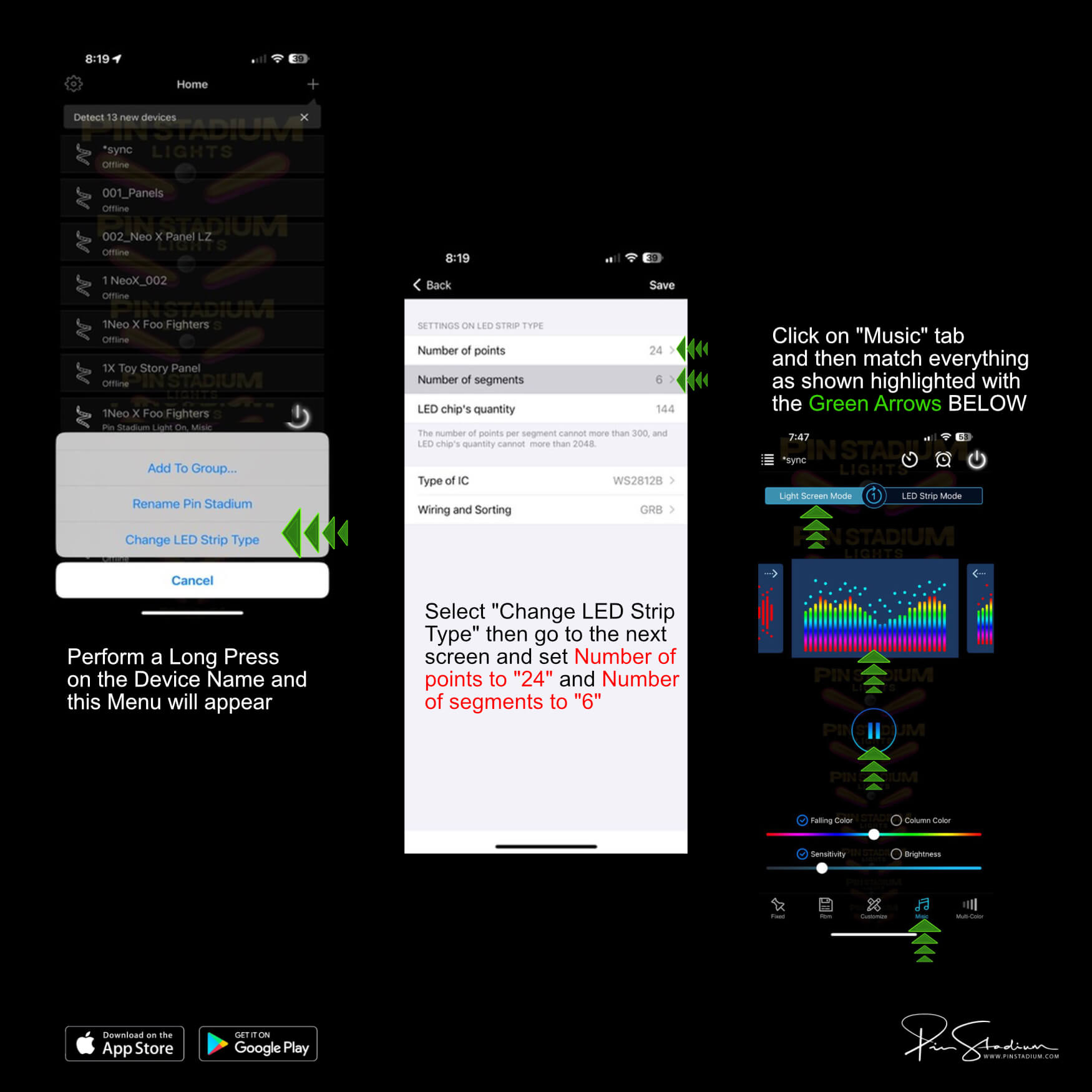
***Lumi-Motion (if you have the “X” versions): Remember this is no need to add the Lumi-Motion to your app as they come pre-programmed to sync automatically with your machine. It is recommended for most users to just keep the stock set up, however if you want to customize them or adjust brightness up or down (factory setting is at 50% brightness) to your liking then there are a lot of possibilities “if” you are a tinkerer and willing to explore. You would simply pull “in and out” the Power cable the goes into the Lumi-Motion module to reset it. Then you will need to wait about 30 -60 seconds for the “LedNet****” network to show up, then add it as you would any Pin Stadium product. Be sure to label it something that is easily identifiable like “pinball name”(Lumi) etc. Then simply do a Long Press on the Device name from the Home Screen and select “Change LED Strip Type” to match the values in the PICTURE BELOW and click “Save” when done. It is suggested to name it something unique like “pinball name”(Lumi) or something along those lines so you will be able to easily identify it in the future. Once connected make you go to “Music” tab located on the bottom of the app. Then select “Device Microphone” and hit the play button. At the tap on “Light Screen Mode” and select the first colorful spectrum setting as shown in the pic below:
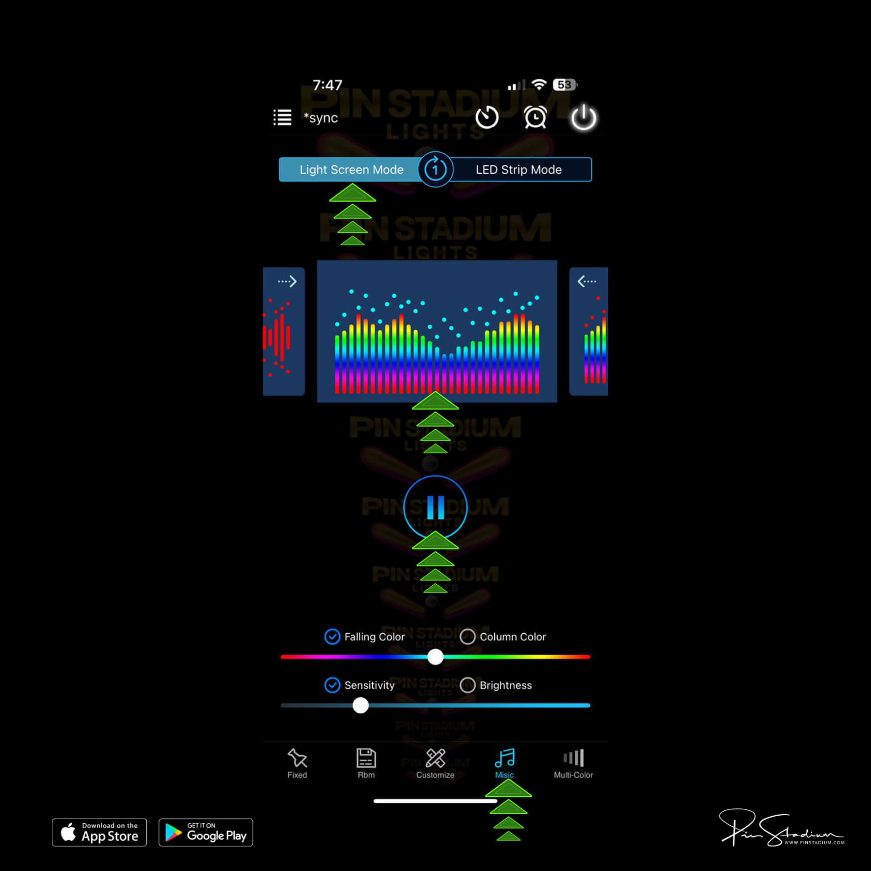
You can adjust the brightness and sensitivity to your liking after a few games. The default brightness is turned up to 5% and it is suggested that you adjust them DOWN to your preferred level as the Lumi-Motion lights are intentionally made to be seen but NOT USED for the main playfield illumination and the higher the Sensitivity, the more intense the effect on the lights. There is a separate set of lights on the lights bars for that and that will be the GI lights controlled from the USB GI module. The Lumi-Motion have the power to light up the entire playfield but their design is to add live motion effects/movement to the playfield. Understanding this is vital so that you know how to properly use, view, and observe the functionally of these lights as the Neo “X” Panels are a new beat in our line up with it’s own set of rules! The Lumi-Motion are there to impress you and not necessarily be as bright as they can be, as 100% is intense and you normally don’t want to have them up that high, but hey you are in control and there are no rules at that point. This section above is to cover the customers that may be thinking “I can see the lights on the side when I am playing and they are so bright” ;). Well it is only the Lumi-Motion lights and it is by design!!
Note: It is highly recommended that you plug your pinball machine into a wall outlet controlled by a switch or using a power strip and turn your game On/Off that way. Otherwise there is a good chance that the Lumi-Motion will be picking up ambient sound in the room when the game is “off” otherwise.
Customization: Adjust to your liking as always and you can feel free to try other effects and patterns if you like, but this is to be done at your own journey and exploration. There is no documentation and instructions on these as it’s self explanatory when you make the changes you see the effects. The screenshot of the suggested effect above shows the one that gives the best overall results in our opinion, but hey you may find something better you like and even can customize them specific ones too! You’ve got option as always with Pin Stadium products.
Guns N’ Roses
- Click Here: For GI use the wire taps on the “B” wire on the right spotlight
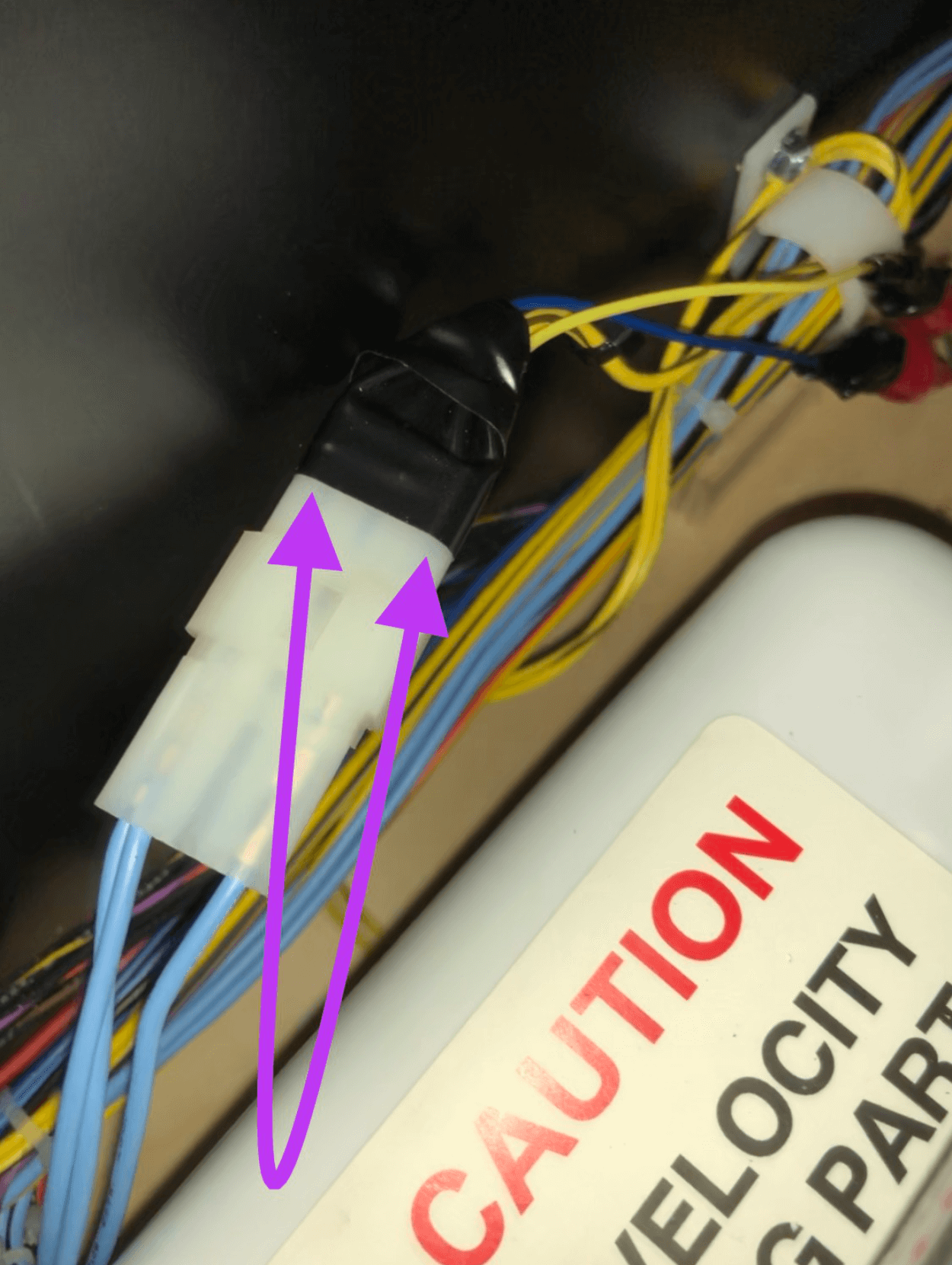
- Flasher: Shaker Motor-> Use the alligator clips on the yellow wires going into the shaker connector. One part of the clip will be inside the connector touching the metal part of the wire and the other clip will be on the outside of the white connector. *Important: Put some electrical tape over the connection to protect it!! Click Here
WOZ
- ECLE(Emerald City LE): Click Here
- Non 2.0 GI/Flashers: Click Here
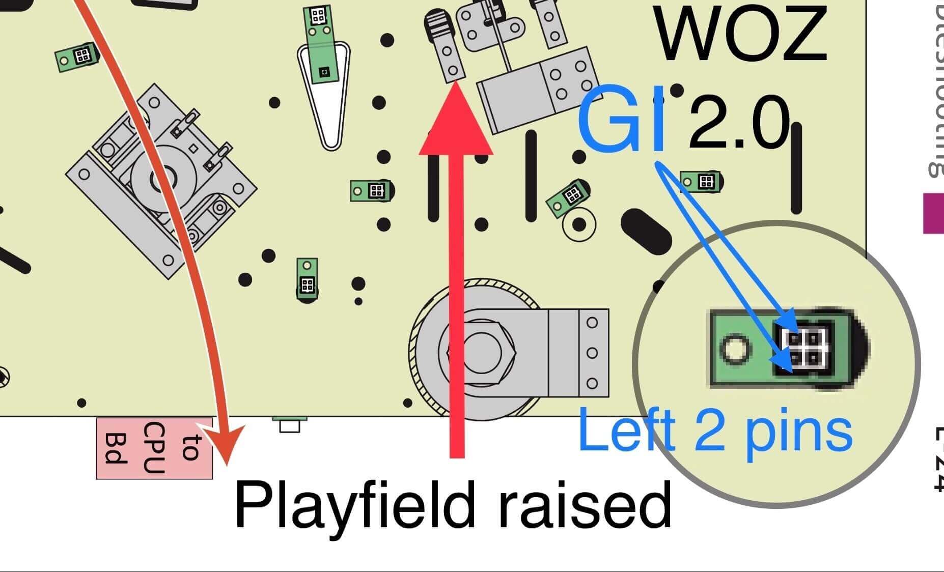
- 2.0 GI/Flashers: Click Here for the flasher and for the GI you need to connect to Click Here
This will show you where the witch flasher plug is located and how the connection will look once you add the “Y” adapter: Click Here
Location of flashers for all versions of WOZ
Trace the red LED witch flasher wires (it the LED to the right if you are looking down on her from above) to the flat ribbon cable that connects to them. This ribbon cable looks like a 1/4” wide camera film that then goes under the playfield and turns into a red and red/black wire which terminates into a a white 3 pin Molex connectors with blue wires coming out.
Hobbit
- GI/Flashers: Click Here
Dialed In
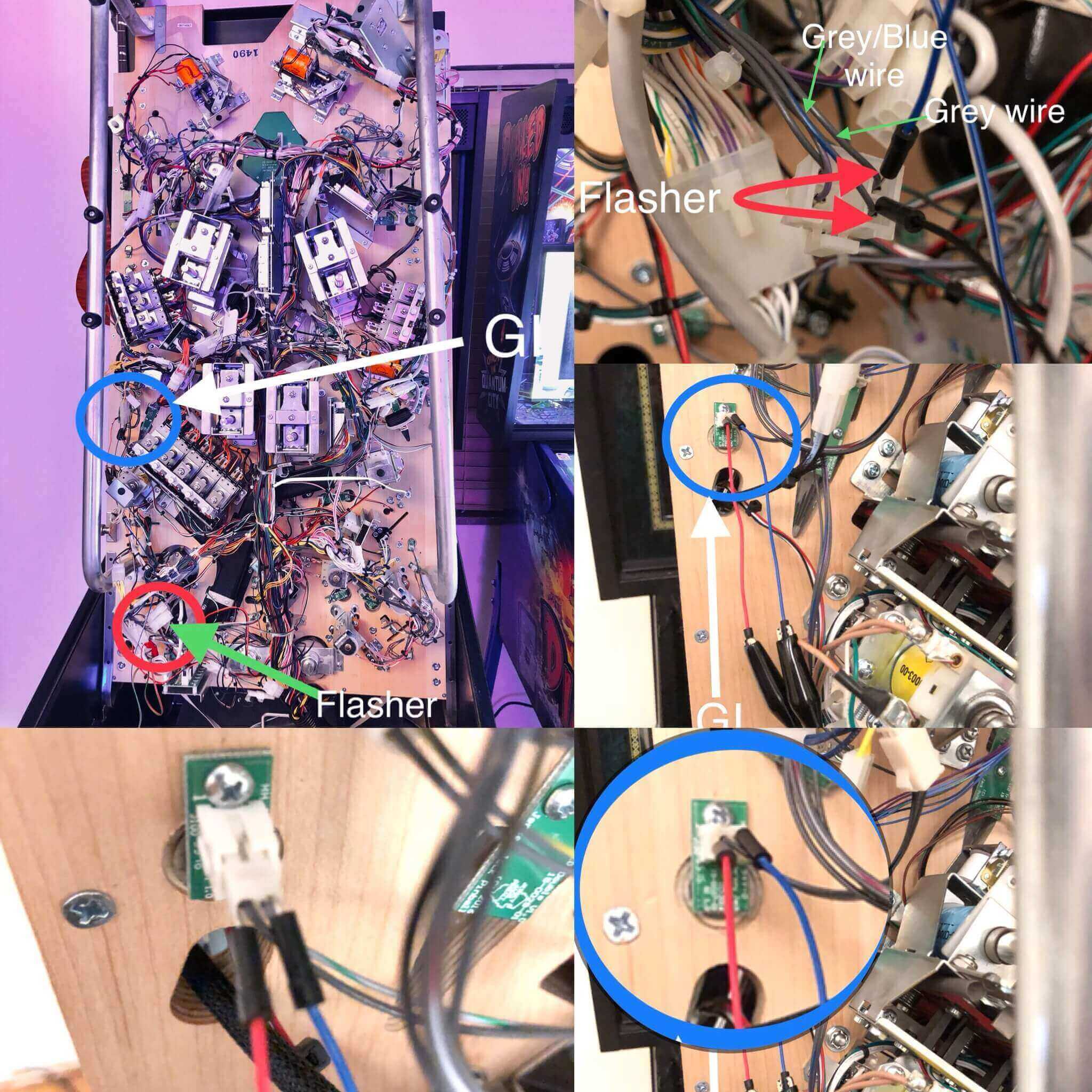
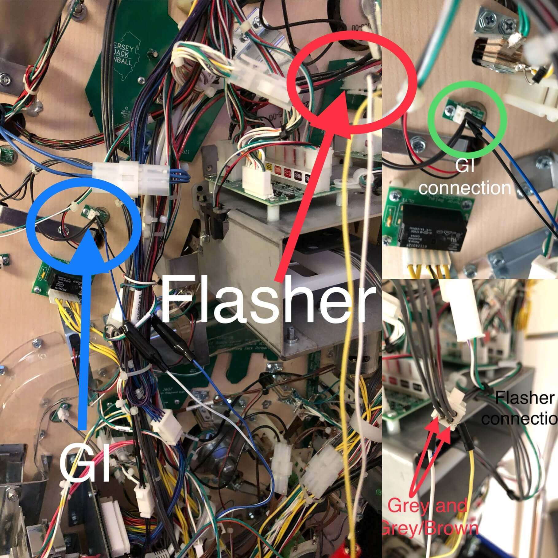
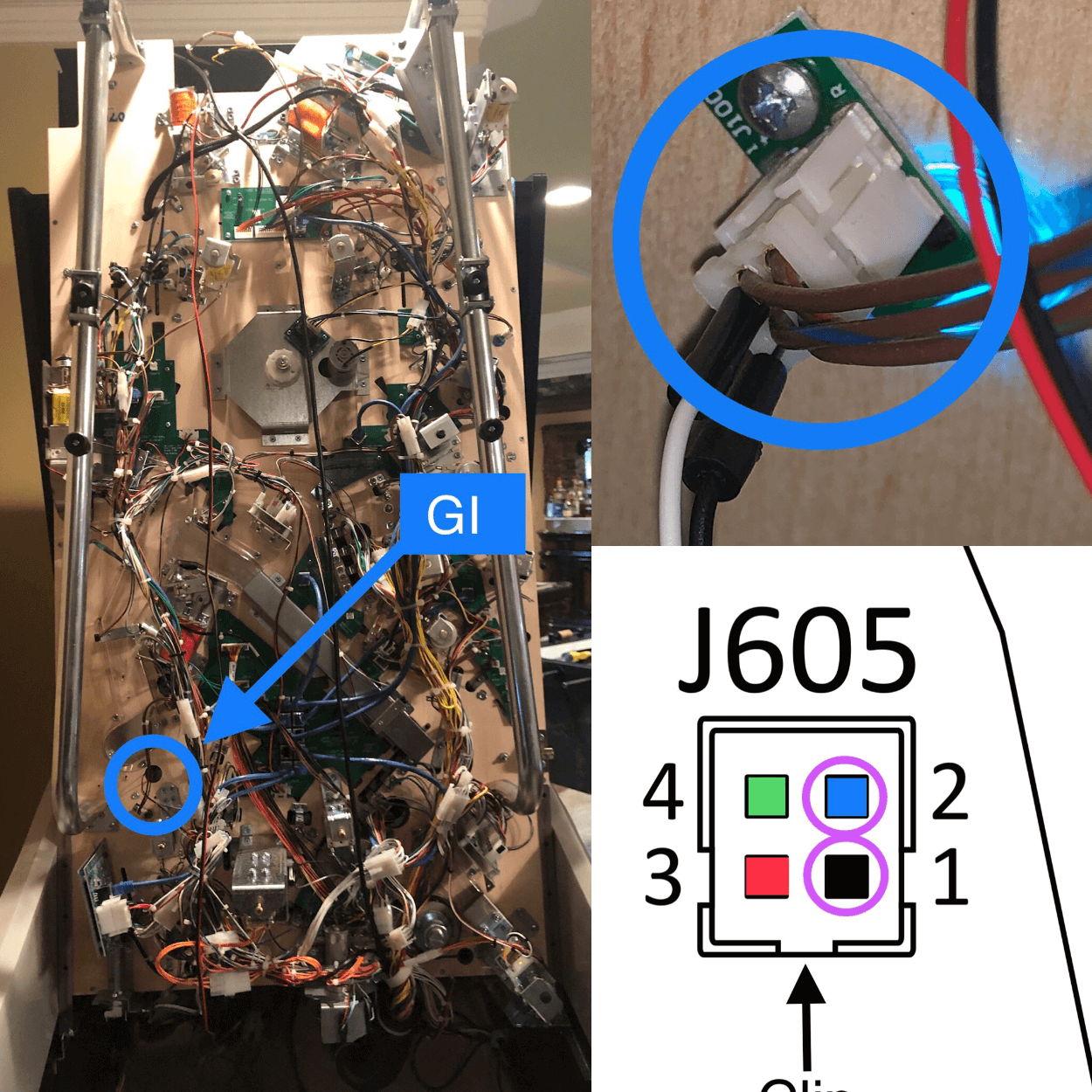
- GI/Flashers: Click Here
Pirates of the Caribbean
- GI: Option 1: Tap any one of the playfield white spotlights using the wire taps(GI on most all the time) Click Here. Option 2: alternative is with more GI interaction : Click Here You can try either as it is personal preference. I like the spotlights connection personally.
- Flasher: Shaker Motor-> Use the provided shaker motor Konekt adapter on the yellow wires going into the shaker connector. Simply unplug the connection and plug the Konekt adapter inline with the factory shake connectors Click Here Note: If you don’t have a shaker motor you can still use this and just be sure to turn the shaker “on” in your factory settings menu. For the Orions Belt Flashers: Click Here Then for the flashers I have color coded with arrows were to trigger for that. The Black cable cable solder together with the wire taps will go to Black on the machine’s connector, the wire tap connector to the Red/Black cable will go to the cable with the Red stripe on the machines, BUT the Green will go to Blue and Blue to Green(yes this is correct ;)
Willy Wonka
- GI: Tap any one of the playfield white spotlights using the wire taps(GI on most all the time) Click Here.
- Flasher: Shaker Motor-> Use the provided shaker motor Konekt adapter on the yellow wires going into the shaker connector. Simply unplug the connection and plug the Konekt adapter inline with the factory shake connectors Click Here Note: If you don’t have a shaker motor you can still use this and just be sure to turn the shaker “on” in your factory settings menu.
*Note: For models made in 2020-up CGC has changed the wiring when the Royal Editions came out. You will use either the “Royal” or “Non-Royal” depending on which one you have. All others made prior will be the “Original” installation listed on the bottom.
Royal:
GI: Look in the area where the “Green” arrow is on the left side of the picture and then locate the connector labeled “GI3”. Next you will use insert the wire taps from behind(pressure fit them in with those wires) on the Black and Yellow wire then clip the black alligator clips from the Pin Stadium Blue and White cable.
Flasher: In that same area located the connector labeled “FL17” (it is 2 connectors above the one you just did for the GI). Next you will use insert the wire taps on the Black and Yellow wire then clip the red alligator clips from the Pin Stadium Red and Green cable. That’s it for this part!!

Original:
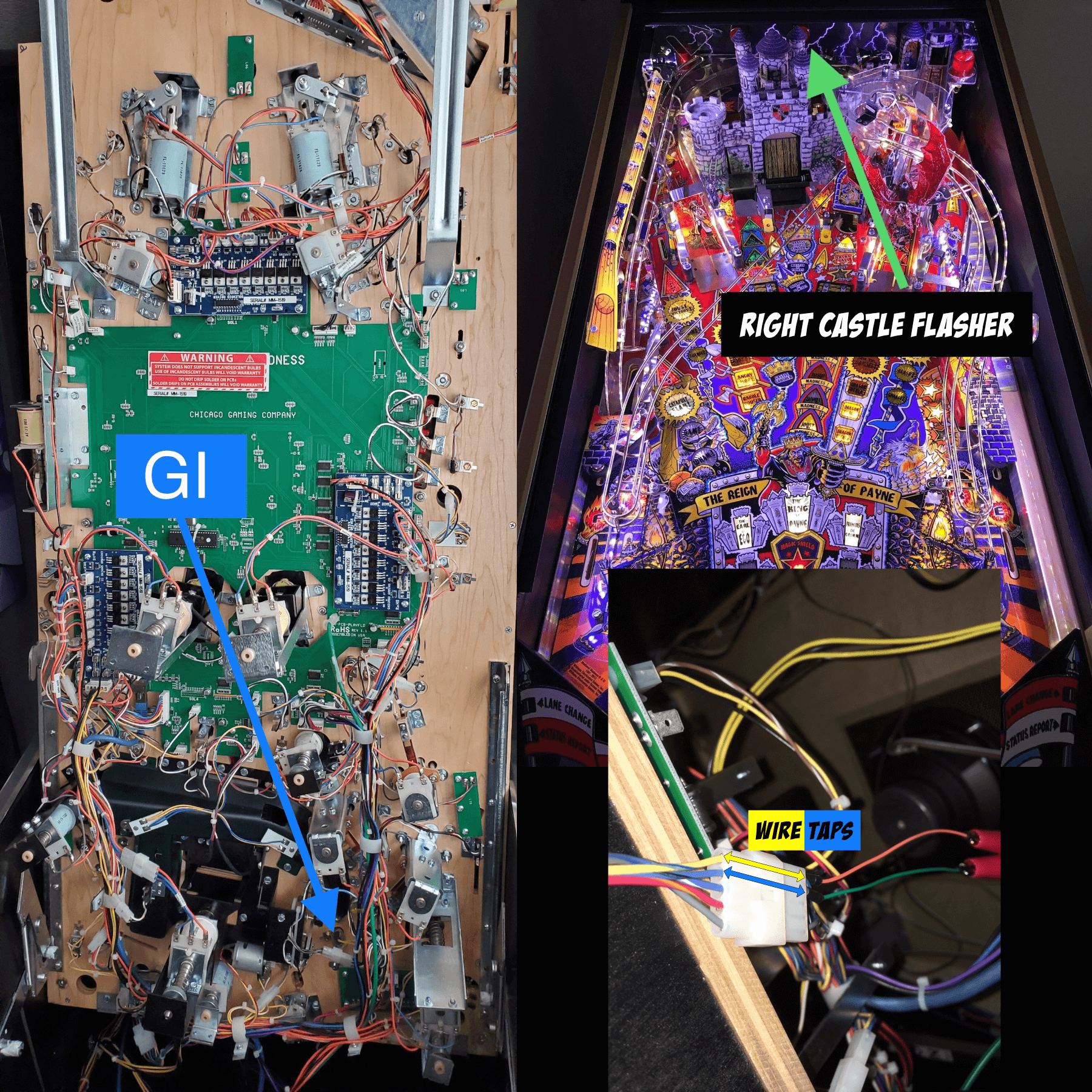
GI: You will use the wire taps to connect onto any White GI bulb. A common one to use is the GI bulb in between the lanes above the pop bumpers (blue arrow in pic below).
Flasher: The Right Castle flasher is located on the backboard of the playfield (red dome to the right of the castle). Trace the two wires from that flasher dome to the white connector, then use the wire taps (per wire taps instructions above, by inserting them behind where the wire goes into the connector) on the Yellow and Blue wires in the connector.

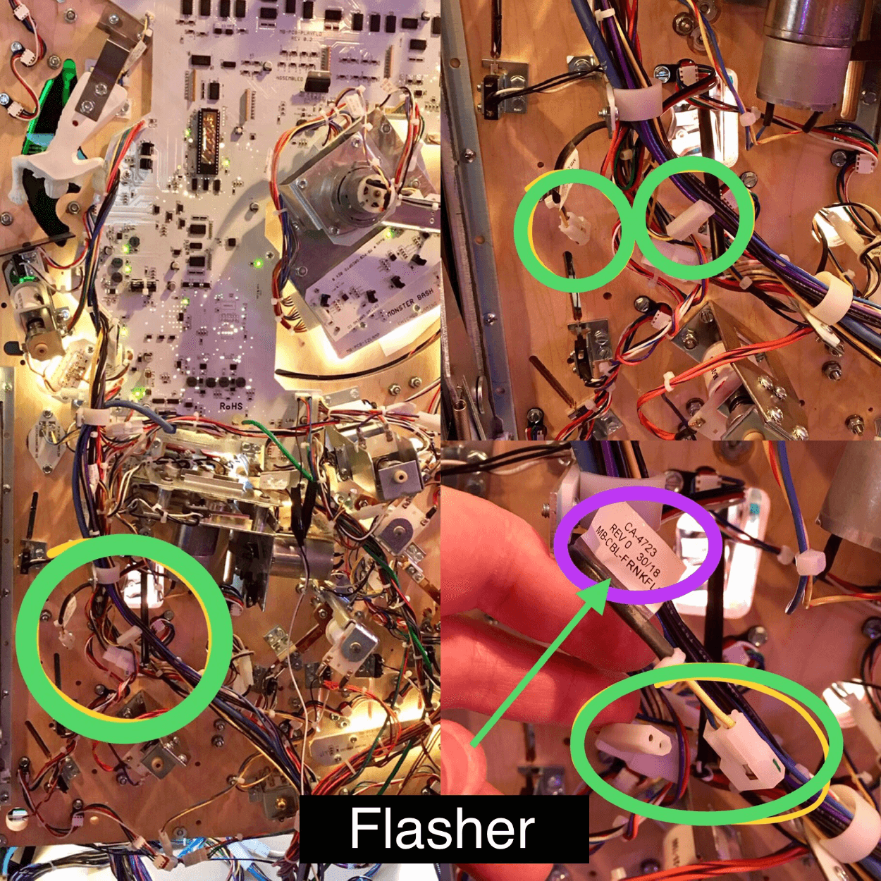
Monster Bash Remake:
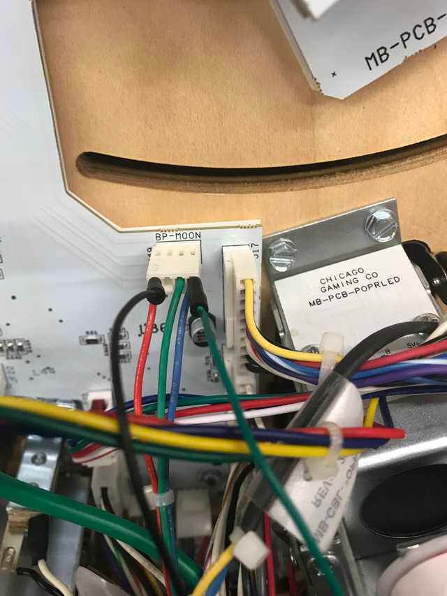
GI: You will use the wire taps to connect into the “BP Moon”. Simply insert one in the “Red” and the other in the “Blue” from the Blue/White Pin Stadium GI cable.
- Flasher: The best place is for the Frankenstein flasher. Trace the 2 wires from the purple orbs down to down underneath the playfield to the connector and use the wire taps there by inserting them behind the wire and then clipping on to them with the alligator clips:
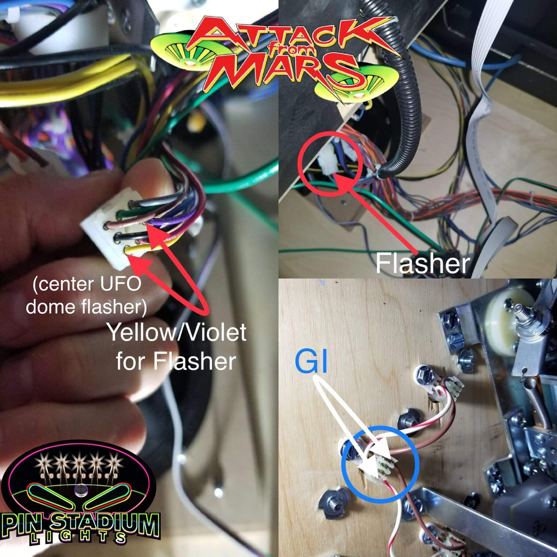
Attack From Mars Remake:
- GI: You will use the wire taps to connect the GI Blue/White cables. Simply unscrew a GI connector (one screw) on AFMR (there are some about halfway down on the right) and then unplug it (machine off to be safe). Now insert the ends of the wire taps into the outside females holes were the GI connectors plug in. Note: It is best to hold the connector vertical, then insert about 1/8″ of the wire tap end in the hole then bend it over so it hangs. Then do that for the opposite side too.Note: Polarity does not matter, so as long as you have the wire taps in good, the Pin Stadium GI module will figure out the polarity for you. |Next close up the GI connector on the wire taps while they are inserted (this is why it is important to hold it vertical so that they will stay in as you put the other end of the connector back together). The wire taps are now “pressure fitted” in safely and securely. Now simply bend the opposite ends of the wire taps all the way over on top of the black barrel so that it is thick enough for you to clip the alligator clips onto. (See instructions further down on this page for pictures and an explanation of how to properly use the wire taps).
Good job!!
- Flasher: Now you are ready to connect the Red/Green Pin Stadium Flasher cables to the “Center Saucer” Dome connectors. Trace the wires that come down from the UFO Saucer under the playfield towards the back and you will see a multiple wire connector (in pictures below) that has Yellow and Violet(Purple) wires coming out of it. Simply insert the wire taps in from behind and pressure fit them into each of those. Polarity does not matter here either.
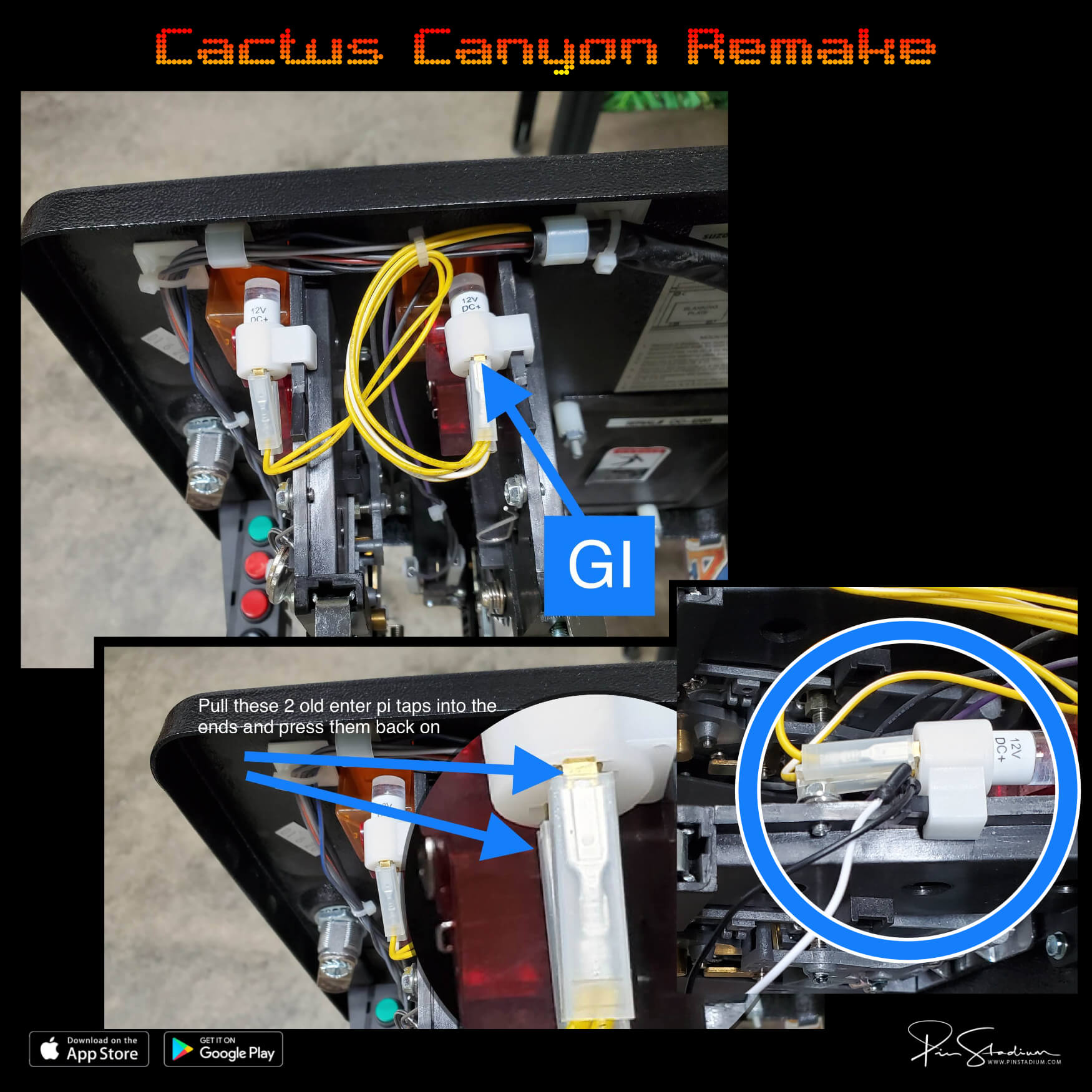
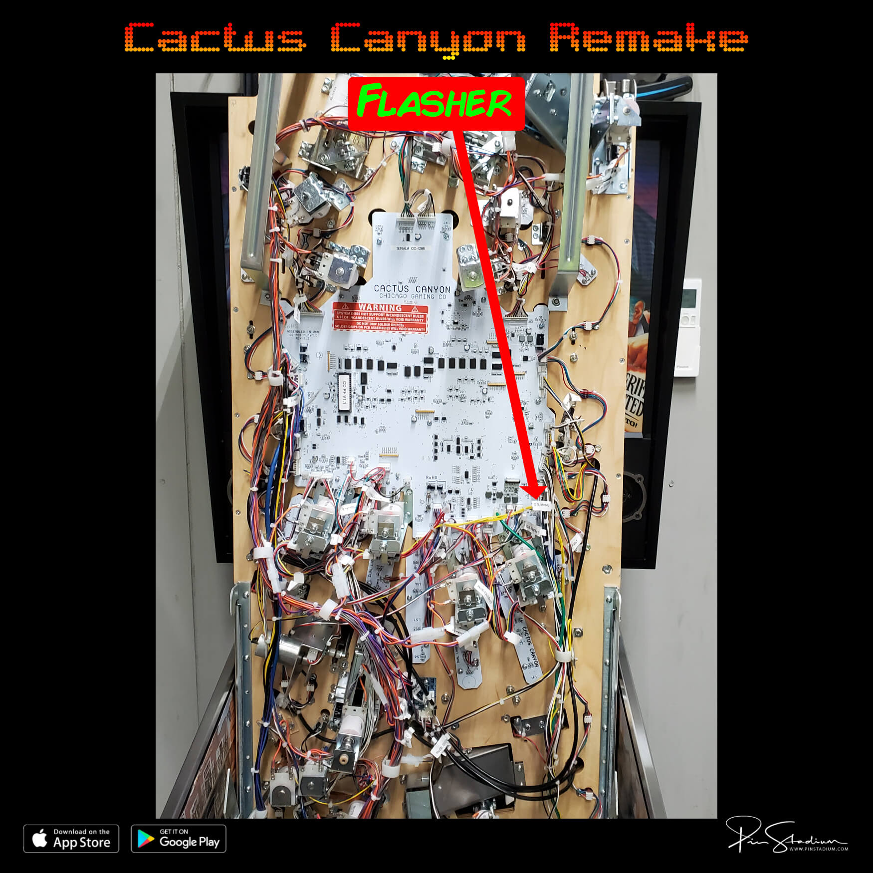
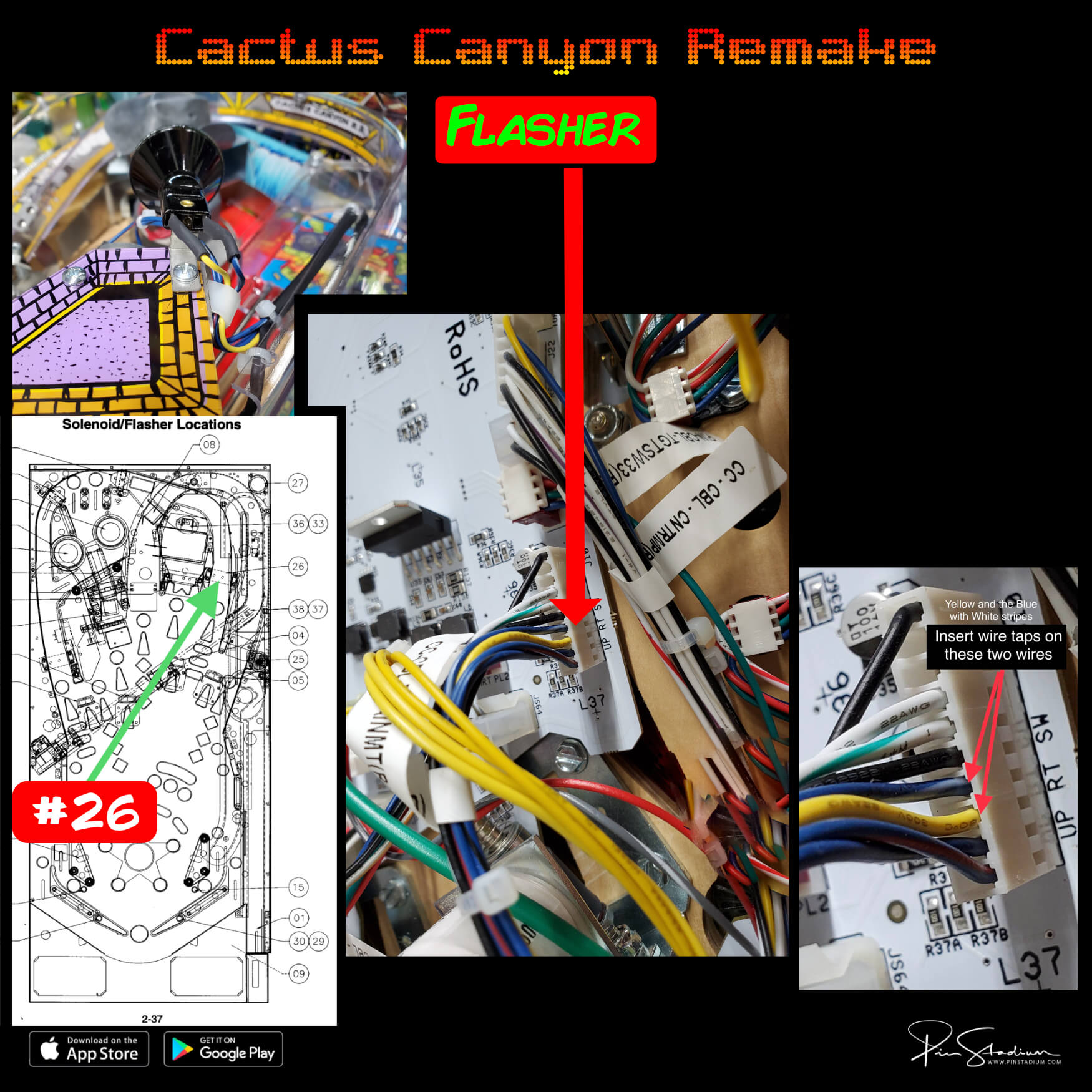
Cactus Canyon Remake:
- GI: Trigger from the left coin door slot bulb (for best wire management purposes) using the wire taps on each of the terminals of the bulb
- Flasher: Locate Spotlight #26 near Bart by inner right ramp. Trace the blue and yellow wires down connector under the playfield and insert the wire taps as shown below
Spooky
- Rob Zombie: Click Here (for power run a power cord into the machine from the wall through one of the screens in the bottom)
- TNA: Click Here (for power run a power cord into the machine from the wall through one of the screens in the bottom)
- Alice Cooper’s Nightmare Castle (ACNC): For the GI trigger connect to the coin door slot bulb. For the UV+Glow you will trigger from the shaker motor.
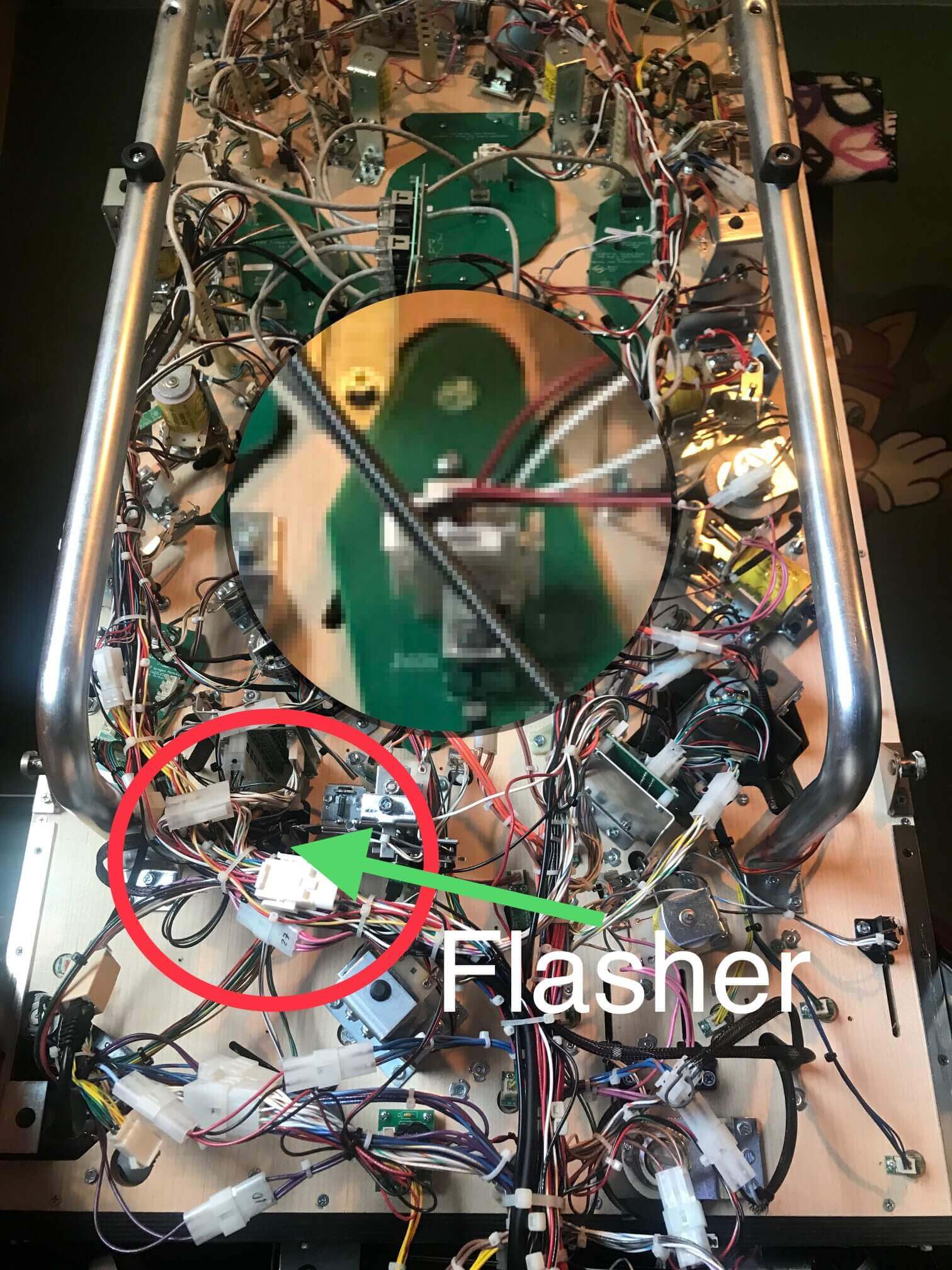
- Rick and Morty: For the GI trigger find this GI board. Use the wire taps on the wires labeled “+” and “G” and in order for this to work you will simply need to unplug the connector from the bottom right bulb show in attached GI pic. Use the bottom right one so it is discreet and not noticeable. For the UV+Glow you will trigger from the shaker motor
- Scooby Doo, Texas Chainsaw, Halloween, Evil Dead: For the GI trigger you will use the 2 pin adapter to connect to the spotlight locate near the corner of the apron For the UV+Glow you will trigger from (ignore the GI label in this pic as you will trigger from the coin door bulb) the shaker motor
Pinball Brothers
Alien
- Run the Power from your wall (plug it into your wall outlet) up into the cabinet(since this machine does not have a service port). For the GI (Blue and White cable) trigger location you can trigger from bulb on the coin door slot like in this video: Click Here Then for the UV+Glow (Red and Green cable trigger with the Konekt adapter on the Xeno Morph: Click Here
American Pinball
ALL Machines
- Preferred method is the GI is triggered from the LED strip in backbox and flasher shown here also(use wires taps on both) or for an alternate GI trigger location you can trigger from bulb on the coin door slot
Dutch Pinball
The Big Lebowski
- Power/GI: Click Here
- Flashers: None unless you want to solder directly to the board on a resistor
Step 2
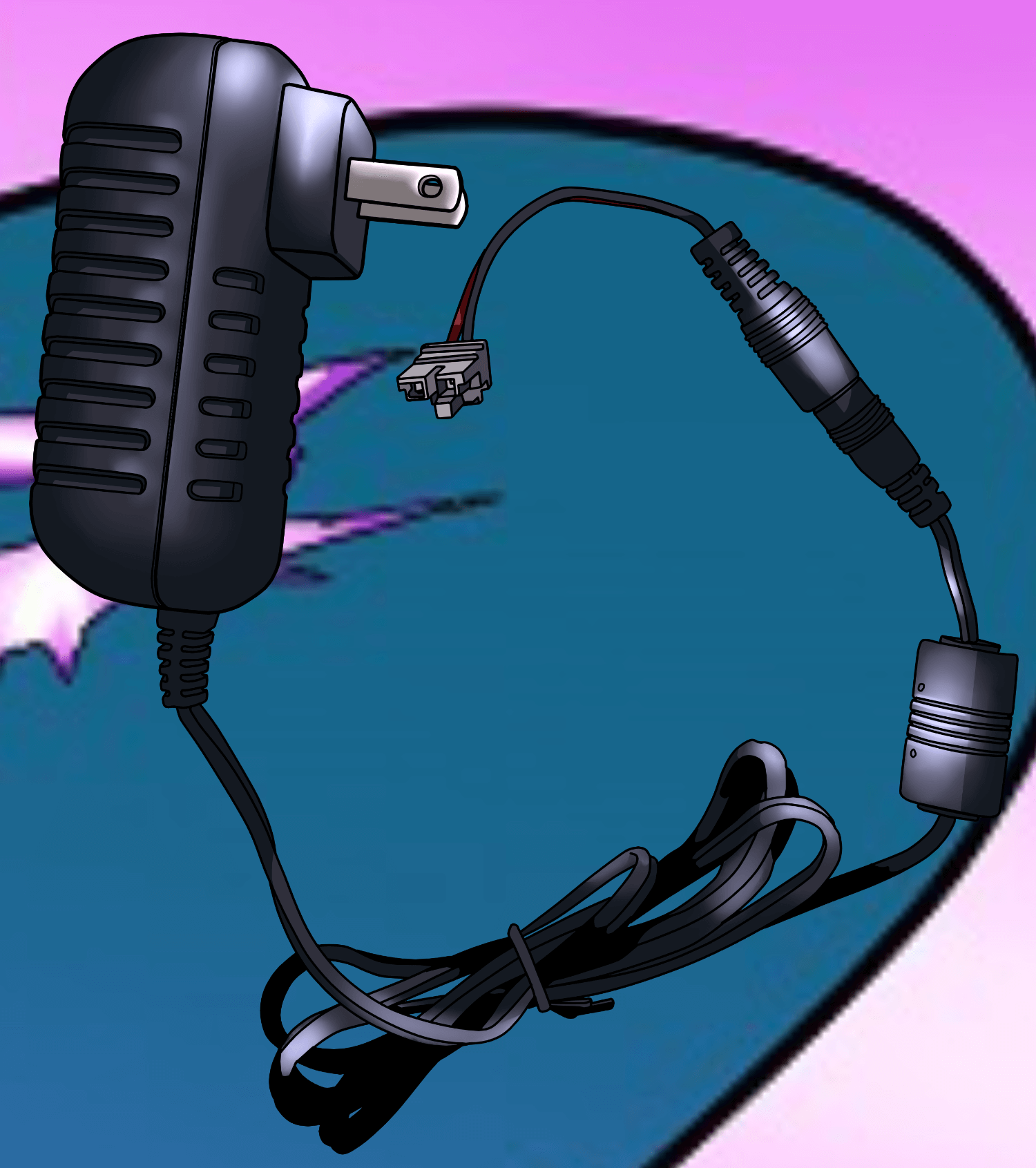
Plug in the Universal Power supply
Plug the Universal Power into your machine’s service port. On most machines it’s in the bottom of the cabinet near the coin door (usually to the right). On newer Sterns (Spike 1 / Spike 2) it’s behind the translite on the lower right. The plug looks like a standard wall outlet.
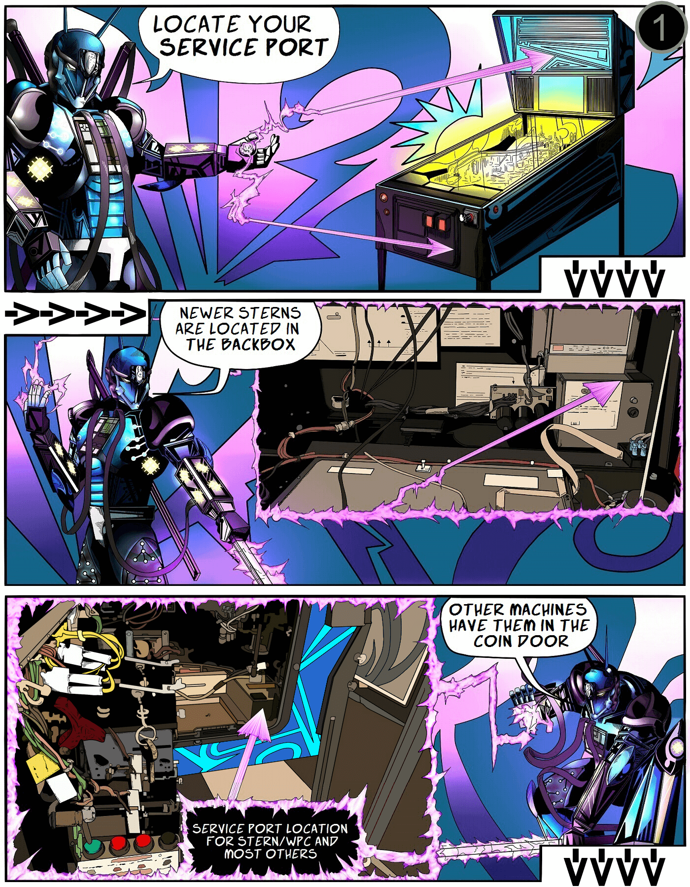
Older machines: some need a service-port adapter cable. If you listed your machine when ordering, we included one. Otherwise, grab one at our store or a local computer shop.
Step 3
Connect the cables to the Pin Stadium GI module
Lower the playfield to its resting angle and rest the GI light bars on top. Now plug the power, GI cable, and Flasher cable into the Pin Stadium GI module:
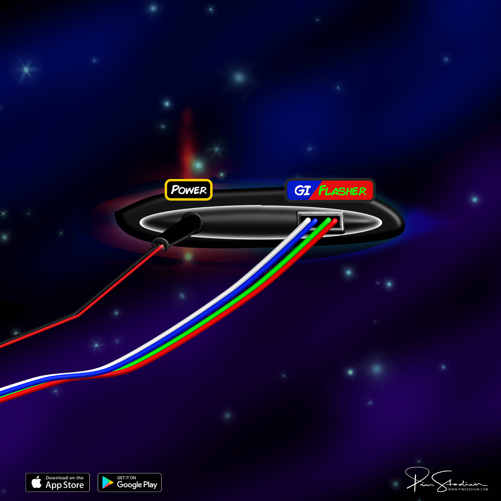
If your module uses a non-USB plug, use this diagram instead.
Step 4
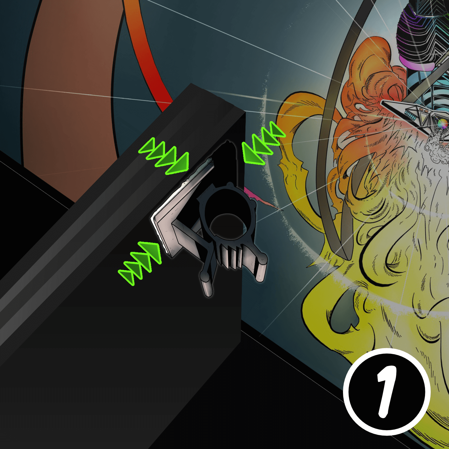
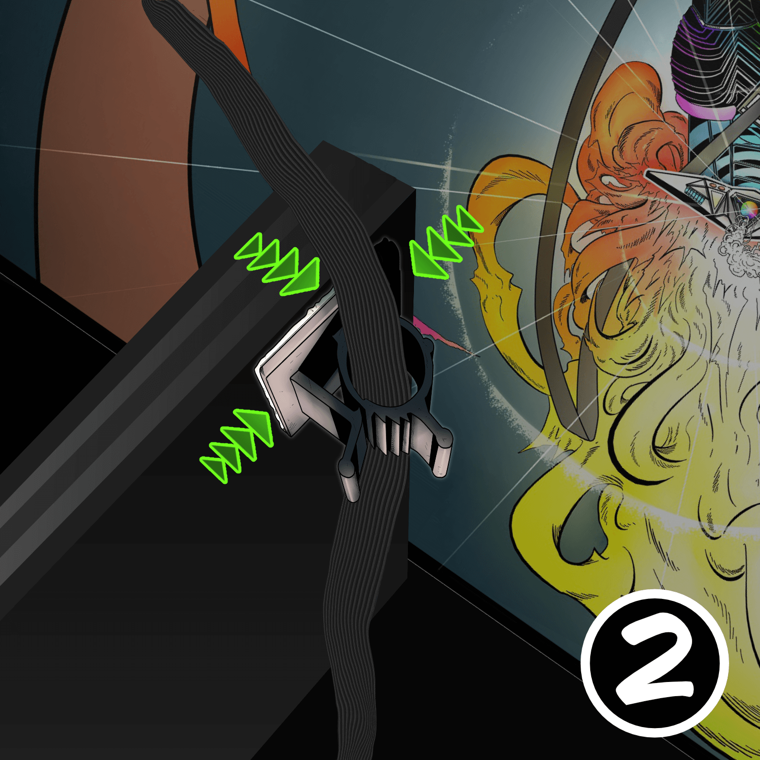
Mount the ribbon-cable clamps and tuck the cables
Place the GI module over the backboard, into the bottom of the cabinet, out of the way of any moving parts.
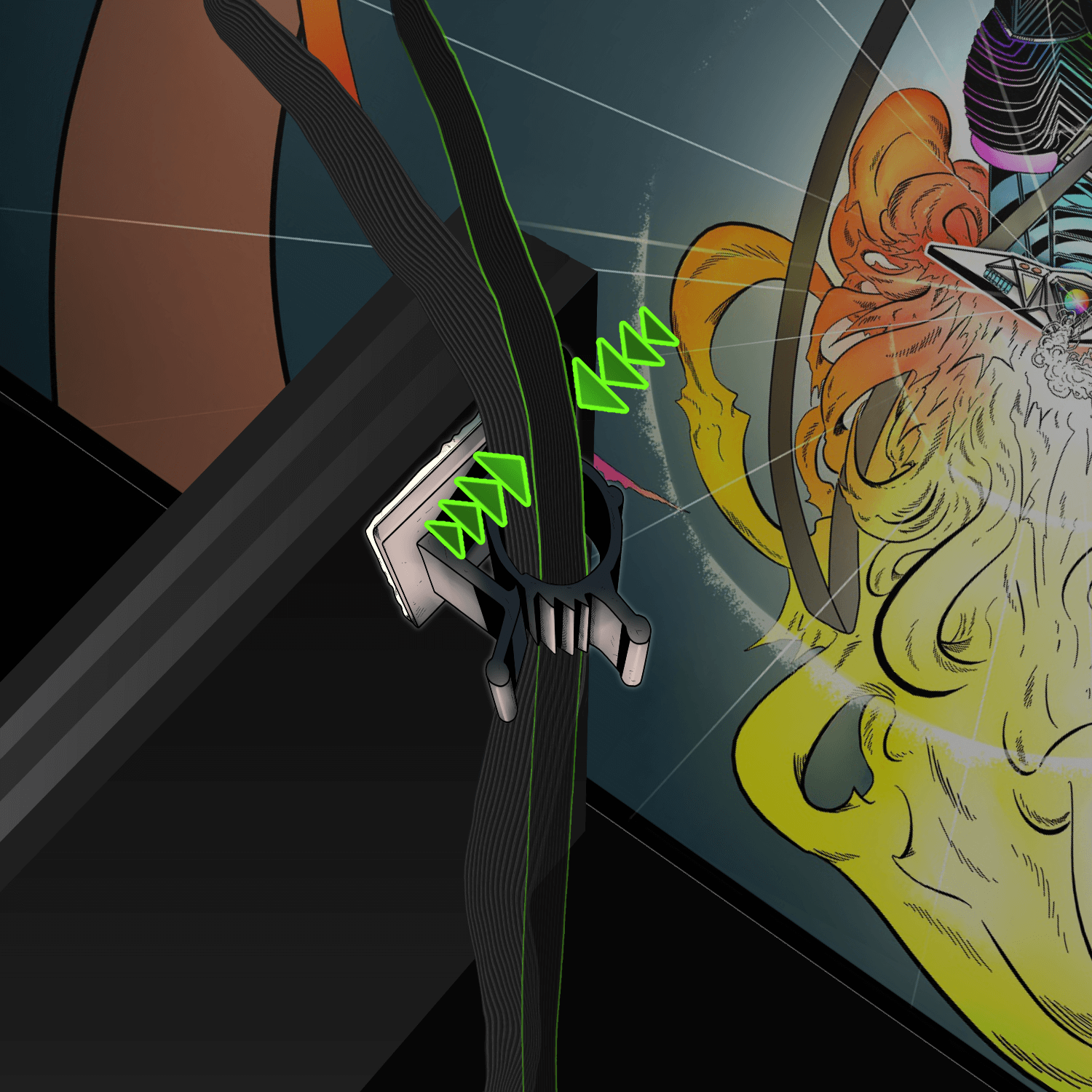
Stick the small adhesive ribbon-cable clamps (from the accessory packet) to the upper-left and upper-right corners of the back of the playfield. These clamps guide the ribbon cables and prevent them from being pinched.
Pro tip: fold the ribbon cable in half lengthwise — it slides into the clamp easier. Leave about 6–8 inches of cable between the clamp and the back of the light bar, with about 1 inch of slack.
Step 5
Prep the cabinet walls (and install Xeno Mounts first, if you have them)
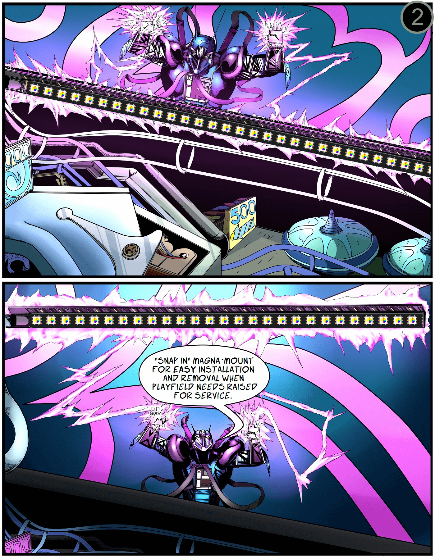
Lower the playfield to its level resting position. Use the alcohol wipe to clean the cabinet wall just below the playfield-glass track — about 2 inches down. It must be completely dry and dust-free for the Magna-Mounts to bond.
Position the GI lights 1/16″ below the glass channel, far enough back to hide the ribbon cable and clear the backbox hinge.

Step 6
Peel, press, repeat (GI bars)
Carefully peel off the white protective backing on the Magna-Mount. Align the GI lights 1/16″ below the channel, far enough back to hide the ribbon cable and clear the backbox hinge.
Press firmly along the entire length of the light channel for maximum adhesion. Repeat for the opposite side.
Step 7
GI bars done — now we install the Fusion flasher bars
Restore the playfield to play position, replace the balls, and clip the GI light bars onto their Magna-Mounts. Replace the glass and lockbar if you want to test the GI bars before continuing.
Take a break, play a game or two, then continue with Step 8 when you’re ready.
Step 8
Remove the playfield glass and balls from the machine, then raise the playfield vertical.
Standard
Next locate your cables:
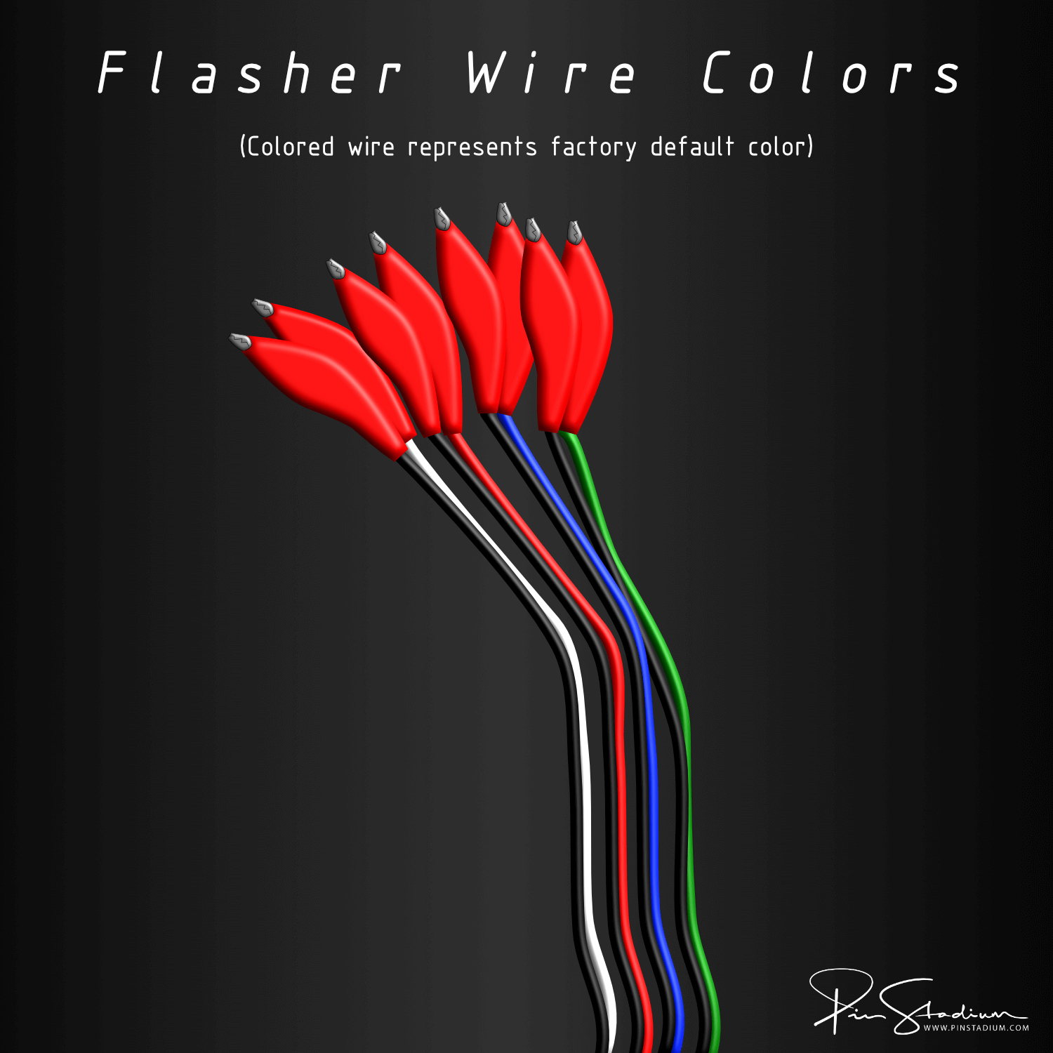
Connect each of the wires to your desired bulb/trigger point (just like you did for the UV+Glow above) using the alligator clips (polarity is not important so it doesn’t matter which side you connect them to).
**Hint: The color of the wires(ref: pic above) represents the factory default color we ship them with, but you can change that later if you decide to. However if you know what color flasher light you want already, then this will give you a headstart and makes things even easier knowing this. For example: Green/Black paired wires are programmed “Green” by default, Red/Black wires are “Red”, etc.
Also if some of your flasher wires have “Y” adapters on the ends that are not alligator clips or if you have extra adapters in your silver accessory bag, then this means that you “may” be able to make a direct connection to the flasher without using the wire taps. It’s optional and not all machines have specific inline adapters, so you may not have these included(we include them if it’s an option and available). However, check to see as you might have some these included specific adapters to match the flasher connector you are trying to trigger from. If so, use them and if not no worries you don’t need them ;) If you have these “Konekt” adapters then simply unplug the factory connection to the flasher and plug it into the Konekt “Y” adapter and the other end you will plug in our cable. Regardless, the alligator clips are an excellent all around solution to make any connection you want on any machine.
Note:
In some cases the alligator clips may not be able to reach into your desired location. If you are trying to connect to unreachable terminals then please use the wire tap leads lead (small colored stiff wires with black barrel ends). These are great for tapping in the back of a connector terminal or EVEN BETTER if your flasher connector looks like the one in this video then you can get an even more secure method to connect it. Check out our wire tap video here Optionally if you want a permanent installation then you can solder or wire splice into where you determine is the best location. Also if you see a connector other than an alligator clip, then this means that your have our new Konekt system (if available for your machine) which will allow you to connect to the recommended flasher or GI using a direct factory style plug and play connector to make things even easier. Find the flasher on your machine that matches the connection and you are good to go. Also make sure you connect to a flasher and NOT a GI bulb. If you mistakenly connect the Red/Green UV+Glow cable to a GI then the lights will get very warm and damage the light bars. Also on some machines the flashers are labeled as such but they do not flash, but instead are “On” more than they are “Off” during gameplay or attract mode(when game is one but idle).
Here is how to locate the Flasher and GI:
———–
To find the flasher options(they are numbered) open the coin door and use the buttons to navigate to Settings/Diag/Lamps/Flash. You can then cycle through them (with the volume or flipper buttons) and get a visual locations of where they are located. The machine will also tell you what flasher# you are on too. This helps to makes things even easier using this method. You will need to pull out the white switch located near the hinge of the coin door to activate the high voltage for the flashers. Otherwise they will not flash then.
To help you trace and identify the 2 wires coming from the flasher:
Normally on the Stern machines they are an orange and red wire in most cases. On the screen when you’re in settings it also tell you the factory wires next to the flasher # too. It will also tell you the color of the factory wires on the screen. That way you will know what you are looking for. You can also confirm that you have the correct flasher by unplugging the flasher connection and the flasher bulb on the machine will turn “Off” and then plug it back together and the bulb will flash “On”. This way you will know 100% for sure you’re on the correct one and it is a flasher. Also “never” trigger from a shaker motor on a Stern machine, and only if you are instructed on machines like Jersey Jack Pinball machines, etc.
The Red/Green cable is the UV+Glow, if you are installing Fusions then it will alway have a black cable with a paired colored wire(Red,Green, or Blue etc). Then from that point you can plug in the flasher connection.
As far as the G.I. trigger:
Any white G.I. bulb for the Blue and White cable you can find will be fine. Generally on the Sterns it will have a yellow wire going to it to help you identify that. Just make sure it’s White and not any other colors as it will cause undesirable effects if it’s not White
———–
Play a few games and see which one you would like to connect to or Email Us if you are unsure.
On the opposite end that you plan to clip to, simply fold it over the black barrel so that it has enough width to connect the clip over it. These methods of connection are generally used and can be semi-permanent solutions if done correctly and it is suggested to put some electrical tape over the ends of the alligator clips to keep them insulated when using the wire tap method. Optionally if you want a permanent installation then you can solder or wire splice into where you determine is the best location. With some installations you may be provided with wire taps built into the adapter and no alligator clip is needed.
Wire tap method shown here:
Step 9
Connect the other end of the power splitter(if not done already prior) to the Orion’s Belt Flasher module(black heat shrink board with buttons on it:

Step 10
Lower the playfield to resting angle position on the cabinet and rest the light bars on the playfield.
Step 11
Place the now connected Fusion Flasher Module over the backboard into the bottom of the cabinet out of the way of any moving objects.
Tip: Bend the ribbon cable in half (as shown below) so that it slides easier as you insert it into the cable clamp you install in the earlier steps on the backboard of the playfield. This allow for easier adjustment for slack and helps when you go to tuck it out of site once the playfield is down. You will eventually find a sweet spot that works with each machine. The ribbon cable is designed to be bendable so that you can further tuck it up and out of the way for a nice stealth look.
Step 12
Lower the playfield back down to it’s level resting position and use the included alcohol wipe to clean the area where you will be mounting the light bar. It will need to be very clean and completely dry before proceeding. The wipe is to insure the best adhesion for the Magna-Mount system that hold the light bar to the side of the cabinet. This is a VERY IMPORTANT step as this will insure solid mount. Take your time here on this one please. Also DO NOT remove the other side of the Magna-Mounts from the light bar prior to installation. The light bars are to be installed with them on for two important reasons, one for correct positioning and also for polarity of the mounts. If you take them off and install them there is a good chance you will reverse polarity if they are not put on with the light bars. If polarity it wrong light bars will always shift when you re-attached them and never go in the correct spot. The two magnets fight will against each other.
Notice here, I have roughly marked the length of the lights to know where to clean and positioning of the lights is critical for the best effect and clean factory finished look. The ribbon cable should be tucked just behind and under the back playfield glass receiver channel into the existing Pin Stadium ribbon cable clamp.
Step 13
Carefully peel off the white protective backing for the Magna-Mount system, paying attention to align the lights flush to the bottom of the Pin Stadiums HD-Magna Mount (they should be touching)
Note: DO NOT separate either of the sides the Magna-Mounts from the back of the light bar as it needs to be installed together as the magnetic polarity is set for proper mounting. This is very important!
Press firmly all along the entire length of the light channel with your fingers to create maximum bonding. Repeat for the opposite side of the cabinet. Take your time here as this is a vital part of the install to insure proper mounting.
Step 14 (Finished)
You’re done — light it up
Raise the playfield back to play position, replace the balls, attach both light bar sets (GI + Fusion flashers) to their Magna-Mount backs on the cabinet sides, then replace the glass and lockbar.
Next: download the app and customize your lights
Enjoy the experience — the Fusion is the loudest, brightest setup we make. Post a “before / after” on the Pin Stadium Pinside thread — we love seeing them.
Questions? Email me directly: Contact Pin Stadium
